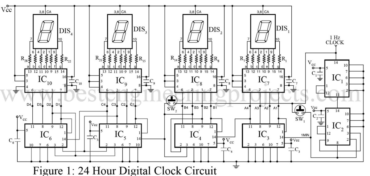
Digital Clock Circuit Diagram Using Counters

Digital Clock Circuit Using Ic 555 And Ic 4026 вђ Diy Electronics Projects These different functions taking place in a digital clock have been illustrated through a block diagram in figure 12.1. according to the figure, the first counter being divided by 60 divides 60hz power signal received on it by 60 and converts it into a 1hz square wave or 1 cycle second square waveform. thus, a 1hz square waveform is received. Using counters in a digital clock circuit diagram can help achieve specific functions such as accepting commands or responding to system events. counters play an integral role in digital clocks, and a thorough understanding of the technology helps reduce the development time of the circuit. all of this information is provided in a digital clock.

6 Digit Digital Clock Circuit Diagram Participated in the. 123d circuits contest. view contest. learning sequential logic design for a digital clock: this instructable is for two purposes 1) to understand and learn the fundamentals of sequential logic 2) use that knowledge to create a digital clock. digital clocks have been built by countless electronics hobbyists over the world. The clock cannot be set to the correct time. hint use additional logic to allow the 1 pps clock to drive the minutes and hours block depending on a button press. below is the block diagram of one solution using a 2 to 1 multiplexer. depending on set, either the 1 pps (pulse per second) or the 1 pph (pulse per hour) clock drives the hour circuit. 8. circuit diagram is obtained and implemented. 2.1 design procedures for easier design, the general circuit of the digital clock is divided into three sub sections namely; 1. second counter circuit section. 2. minute counter circuit section. 3. hours counter circuit section. the flow chart in figure 1 gives step by step. The 1 hz signal is fed into the first dual decade counter [ic3] that runs from 0 9. the binary coded decimal from ic3 is fed into a 4543 [ic4] that is converted for a seven segment display. the block diagram omits showing the drop down resistors, but they're really there. use either 500Ω for a bright display or 1000Ω for a dimmer display.

Digital Clock Circuit Diagram Using Counters 8. circuit diagram is obtained and implemented. 2.1 design procedures for easier design, the general circuit of the digital clock is divided into three sub sections namely; 1. second counter circuit section. 2. minute counter circuit section. 3. hours counter circuit section. the flow chart in figure 1 gives step by step. The 1 hz signal is fed into the first dual decade counter [ic3] that runs from 0 9. the binary coded decimal from ic3 is fed into a 4543 [ic4] that is converted for a seven segment display. the block diagram omits showing the drop down resistors, but they're really there. use either 500Ω for a bright display or 1000Ω for a dimmer display. Synchronous counter circuit . timing diagram synchronous counter. from circuit diagram we see that q0 bit gives response to each falling edge of clock while q1 is dependent on q0, q2 is dependent on q1 and q0 , q3 is dependent on q2,q1 and q0. decade counter. a decade counter counts ten different states and then reset to its initial states. To design a digital clock circuit using counters, an engineer must consider a variety of factors. these include the type of counter being used, the speed of the circuit, and the number of digits that need to be displayed. additionally, the different combinations of logic gates and flip flops should also be designed carefully, as they determine.

24 Hour Digital Clock Circuit Diagram Synchronous counter circuit . timing diagram synchronous counter. from circuit diagram we see that q0 bit gives response to each falling edge of clock while q1 is dependent on q0, q2 is dependent on q1 and q0 , q3 is dependent on q2,q1 and q0. decade counter. a decade counter counts ten different states and then reset to its initial states. To design a digital clock circuit using counters, an engineer must consider a variety of factors. these include the type of counter being used, the speed of the circuit, and the number of digits that need to be displayed. additionally, the different combinations of logic gates and flip flops should also be designed carefully, as they determine.

Digital Clock Circuit Diagram Using Counters

Comments are closed.