Digital Clock Using 4026 Ic Electroniks Day Youtube

Dld Projects Digital Clock Using 4026 Counter Ic Youtube 24 hours digital clock using 4026 ic and 555 timer with 7 segment displays.like share and subscribedownload simulation file:for more details visit website:ht. Date: march 1, 2021main components:1. cd 4026be (6) the 4026 is a decade counter integrated circuit (ic) with decoded outputs for driving a common cathode s.

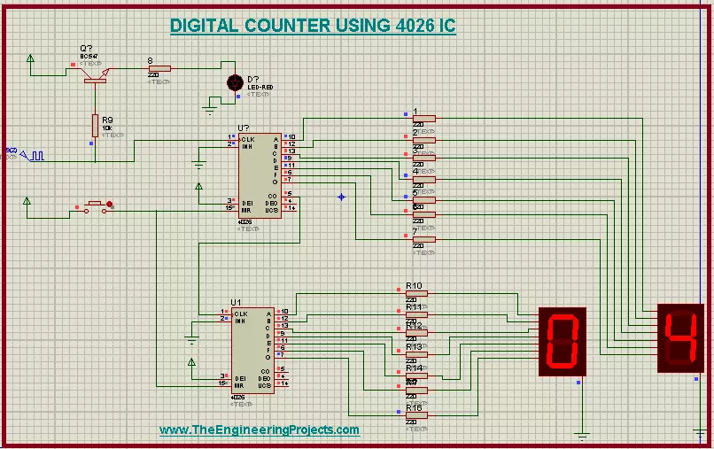
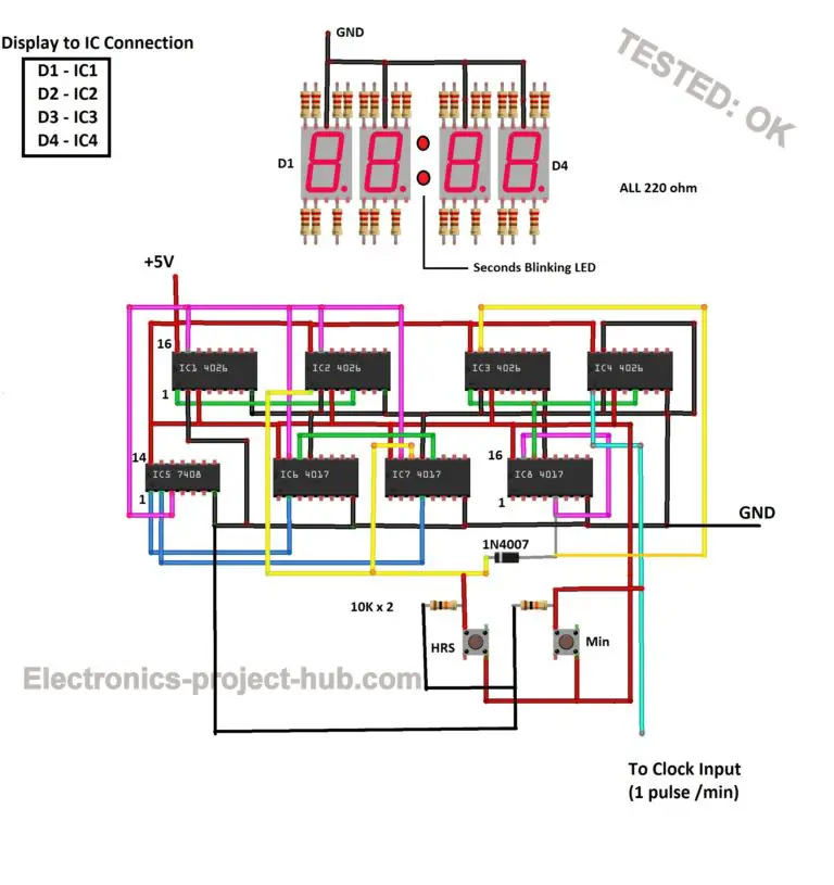
Digit Electronic Counter Discounted Shop Stylebyemilyhenderson Project material & circuit diagram link : drive.google drive folders 1uwoqqiyamzzwusykz58avot64grl to5?usp=sharingit is a 24 hour digital clock t. All the circuit is power at 5v. note: the accuracy of this digital clock depends on how accurate you bring the ic 555 pulse to 1 hz. ic 4026 to 7 segment display connection: ic 4026 to 7 segment display connection. you need to connect the 220 ohm resistor to each segment as shown above. The two switch are used to set the time and is achieved using 4060 pin by increasing the frequency that is being fed to 4026 ic. the first switch which has lower frequency of the two is used to set the minutes in the clock. the second switch which has higher frequency is used to set the hours in the clock. 2. The proposed 7 segment clock circuit is inexpensive and even beginner in arduino can accomplish it with ease. this clock consists of four 7 segment displays, two for hours and two for minutes. the display is paired with ic 4026 which is designed for driving 7 segment displays. each ic 4026 is controlled by arduino.

Digital Clock Circuit Diagram Using 7 Segment Display The two switch are used to set the time and is achieved using 4060 pin by increasing the frequency that is being fed to 4026 ic. the first switch which has lower frequency of the two is used to set the minutes in the clock. the second switch which has higher frequency is used to set the hours in the clock. 2. The proposed 7 segment clock circuit is inexpensive and even beginner in arduino can accomplish it with ease. this clock consists of four 7 segment displays, two for hours and two for minutes. the display is paired with ic 4026 which is designed for driving 7 segment displays. each ic 4026 is controlled by arduino. Step 5: placement of ic 4026 [counter] 1 5. if you can build one counter successfully which can count from 0 9, then the rest of the circuit is just replicating the exact same 4026 circuits 5 more times. but doing this there will be few changes to the clock, reset, and the carry out (co) pin of the ic. This circuit diagram is for a seven segment display driven by a 4026 decade counter, which receives the clock signal from a 555 timer ic. if you made the previous circuit to this, which used a push to make (ptm) switch to generate a clock pulse, then this circuit is a step forward and uses a 555 ic in astable mode to generate a slow clock pulse.

Comments are closed.