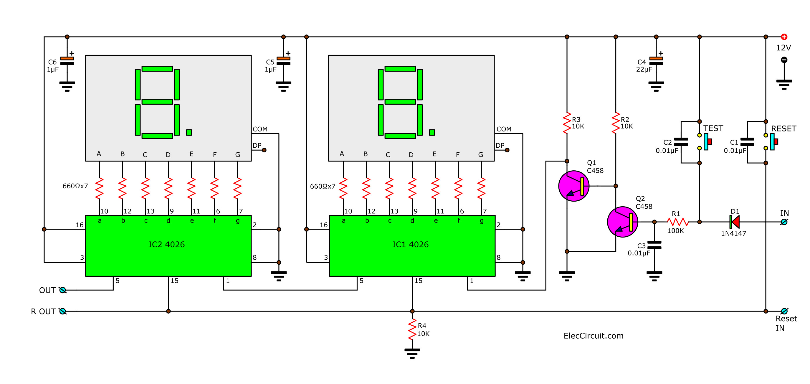
Digital Counter Circuit Diagram

Digital Pulse Counter Circuit Synchronous counter circuit . timing diagram synchronous counter. from circuit diagram we see that q0 bit gives response to each falling edge of clock while q1 is dependent on q0, q2 is dependent on q1 and q0 , q3 is dependent on q2,q1 and q0. decade counter. a decade counter counts ten different states and then reset to its initial states. May 23, 2024 by electrical4u. 💡. key learnings: digital counter definition: a digital counter is defined as an electronic circuit used to count occurrences of events. flip flops: flip flops, like d and jk types, are the building blocks of digital counters. types of counters: counters can be asynchronous, synchronous, up, or down, based on.

2 Digit Simple Digital Counter Circuit Using Cd4026 Synchronous counters. to avoid the latency inherent in the design of a ripple counter, we need to have all the flip flops update at the same time. that means having them all use the same clock signal. as usual, solving a problem isn't without cost. in this case (indeed in many cases in digital circuit design) this takes the form of more circuitry. As the circuit below. the ic1, ic2 cd4026 (cmos counters decade divider integrated circuit). i like this ic. because they can drive led 7 segment directly. recommended: 0 99 counter using ttl 74ls48, 74ls90. which they connected together. ic1 is a unit counter ic. ic2 is a ten digit counter. and both ics will work at rising edged clock only. A digital counter is obtained by arranging the flip flops. these are the applications of flip flops. other than counting, these are used for measuring the frequency as well as time. these are used to increase the addresses in memory. the operation of these devices depends on the single clock applied. these are made of flip fops as basic. Digital counter circuit. the counter comprises two nand gates of cd4011, up down counter cd4510, 7 segment decoder cd4511 and some discrete components. nand gates n1 and n2 are configured in the form of a flip flop. when switch s1 is pressed, pin 4 of gate n2 goes high and generates a low to high clock pulse for counter cd4510.

3 Digit Counter Circuit Diagram A digital counter is obtained by arranging the flip flops. these are the applications of flip flops. other than counting, these are used for measuring the frequency as well as time. these are used to increase the addresses in memory. the operation of these devices depends on the single clock applied. these are made of flip fops as basic. Digital counter circuit. the counter comprises two nand gates of cd4011, up down counter cd4510, 7 segment decoder cd4511 and some discrete components. nand gates n1 and n2 are configured in the form of a flip flop. when switch s1 is pressed, pin 4 of gate n2 goes high and generates a low to high clock pulse for counter cd4510. Counters calculate or note down the number that how many times an event occurred. counters are the crucial hard ware components, and are defined as “the digital circuit which is used to count the number of pulses”. counters are well known to us as “timers”. counter circuits are the best example for the flip flop applications. The above circuit diagram represents a 3 bit johnson counter using a 7474 d flip flop. you can easily extend this circuit up to 4 bit, 5 bit, etc. by adding flip flops after the 3rd flip flop. a single 7474 ic consists of 2 flip flops. so you need two 7474 ics for implementing the johnson ring counter.

99 Counter Circuit Diagram Counters calculate or note down the number that how many times an event occurred. counters are the crucial hard ware components, and are defined as “the digital circuit which is used to count the number of pulses”. counters are well known to us as “timers”. counter circuits are the best example for the flip flop applications. The above circuit diagram represents a 3 bit johnson counter using a 7474 d flip flop. you can easily extend this circuit up to 4 bit, 5 bit, etc. by adding flip flops after the 3rd flip flop. a single 7474 ic consists of 2 flip flops. so you need two 7474 ics for implementing the johnson ring counter.

Comments are closed.