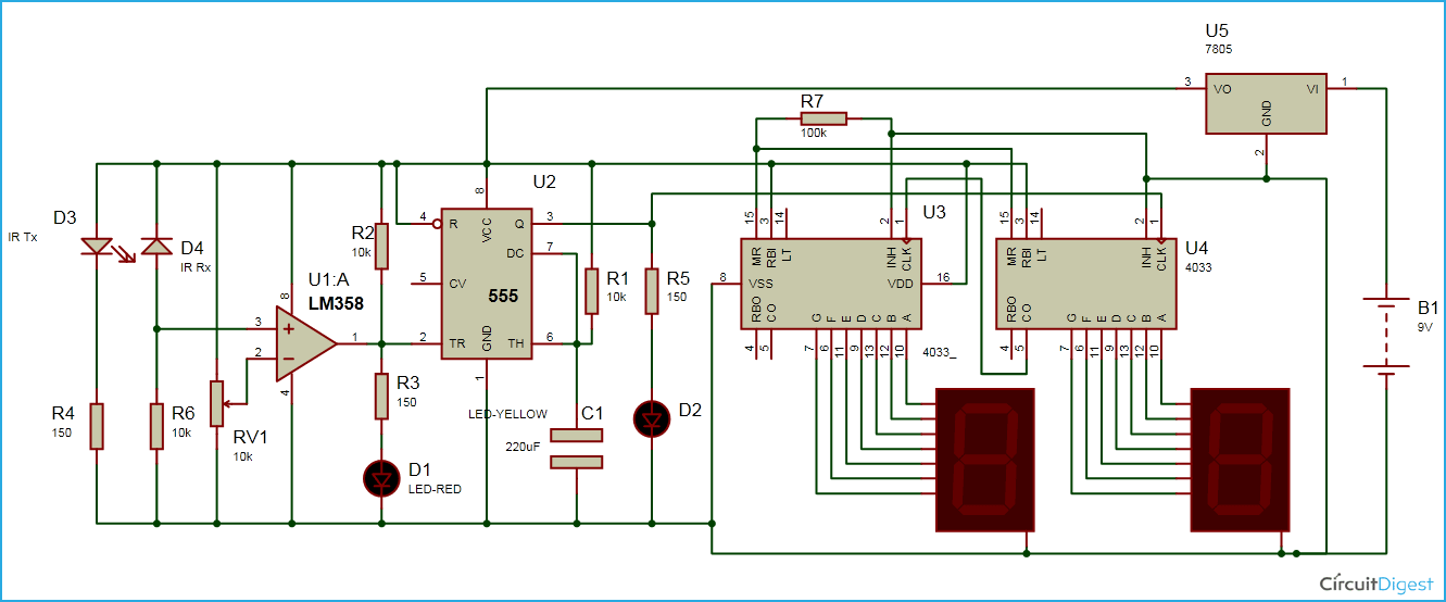
Digital Counter Circuit Diagram Pdf

4026 Manual Digital Counter Circuit Diagram Design combinational logic circuits • combinational logic circuits do not have an internal stored state, i.e., they have no memory. consequently the output is solely a function of the current inputs. • later, we will study circuits having a stored internal state, i.e., sequential logic circuits. A synchronous counter, in contrast to an asynchronous counter, is one whose output bits change state simultaneously, with no ripple. the only way we can build such a counter circuit from j k flip flops is to connect all the clock inputs together, so that each and every flip flop receives the exact same clock pulse at the exact same time:.

Digital Counter Circuit Diagram Pdf Step 1: state diagram. the first step in the design of a counter is to create a state diagram. a state diagram shows the progression of states through which the counter advances when it is clocked. as an example, fig1 19 is a state diagram for a basic 3 bit gray code counter. Shift registers counters synchronous and asynchronous counters modulus counters, up down counters ring counter johnson counter state diagram, state table, state minimization hazards. table of topics s.no topic page no. 3.1 introduction to sequential circuits 3.2 flip flops 3.2.1 sr flip flops. Sequential logic. latches. flip flops. counters until now: we have essentially ignored the issue of time. we have assumed that our digital logic circuits perform their computations instantaneously. our digital logic circuits have been “stateless”. once you present a new input, they forget everything about previous inputs. A counter is a device which stores (and sometimes displays) the number of times a particular event or process has occurred, often in relationship to a clock signal. counters are used in digital electronics for counting purpose, they can count specific event happening in the circuit. for example, in up counter a counter increases count for every.

Digital Pulse Counter Circuit Sequential logic. latches. flip flops. counters until now: we have essentially ignored the issue of time. we have assumed that our digital logic circuits perform their computations instantaneously. our digital logic circuits have been “stateless”. once you present a new input, they forget everything about previous inputs. A counter is a device which stores (and sometimes displays) the number of times a particular event or process has occurred, often in relationship to a clock signal. counters are used in digital electronics for counting purpose, they can count specific event happening in the circuit. for example, in up counter a counter increases count for every. It is often more simple to design sequential circuits if the outputs change only on the either rising (positive going) or falling (negative going) ‘edges’ of the clock (i.e., enable) signal. we can achieve this kind of operation by combining 2 transparent d latches in a so called master slave configuration. Counter circuit are the count modulus, counter stages, output bits, frequency division, asynchronous operation, synchronous operation, and trigger characteristics, as described in sections below. 1. count modulus the count modulus is the total number of states or values generated by the counter as it progresses through its specified sequence.

3 Digit Counter Circuit Diagram It is often more simple to design sequential circuits if the outputs change only on the either rising (positive going) or falling (negative going) ‘edges’ of the clock (i.e., enable) signal. we can achieve this kind of operation by combining 2 transparent d latches in a so called master slave configuration. Counter circuit are the count modulus, counter stages, output bits, frequency division, asynchronous operation, synchronous operation, and trigger characteristics, as described in sections below. 1. count modulus the count modulus is the total number of states or values generated by the counter as it progresses through its specified sequence.

Digital Counter Circuit Diagram

Comments are closed.