Digital Pulse Counter Circuit Diagram

0 To 99 Digital Pulse Counter Circuit The circuit using ics 4518, 4511, and a common cathode display is a binary counter with a decimal output. it can count from 0 to 99 and display the count on a 7 segment display. the ic 4518 is a dual bcd (binary coded decimal) up counter, which means it can count up in decimal from 0 to 99. the two counters are cascaded so that the second. Recently i came to understand the true demand for a multi purpose digital pulse counter. so i designed an east to build digital pulse counter circuit based on some generally available cheap electronic components. the quick microcontroller based design comprises of the following: digispark attiny85 development board (original clone).

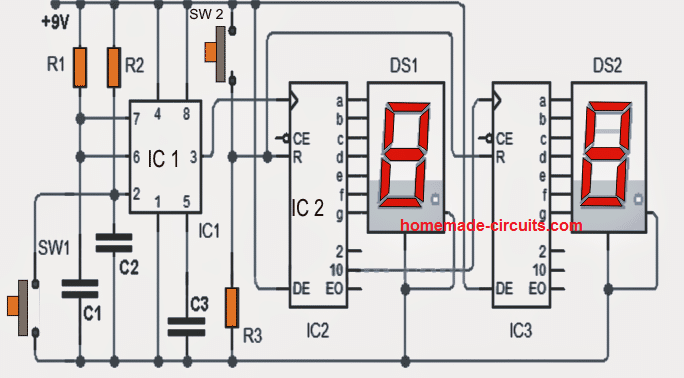
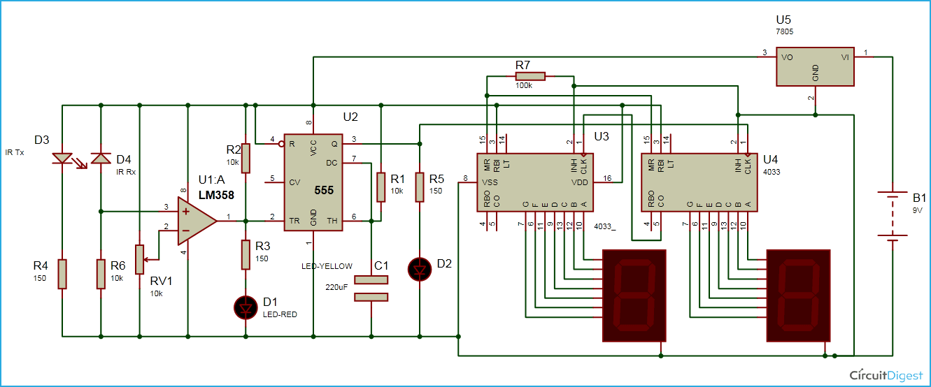
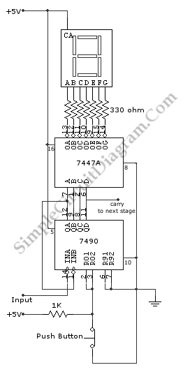
Digital Pulse Counter Circuit The highly recommended 00 99 digital counter turns into easy to carry in places where you require to keep the people organized in some particular order. functioning information of the digital counter as could be known as the circuit uses the widely used 555 ic to genearte the pulse clocks. the pulse counting is conducted with the aid of sw1. It is a cmos seven segment counter ic and can be operated at very low power. it is a decade counter, counts in decimal digits (0 9). it is used to display numbers on seven segment displays and it increment the number by one, when a clock pulse is applied to its pin 1. means more the clock pulse rate, faster the numbers change in 7 segment display. A 4 bit ripple counter is a digital circuit that is used to count the number of pulses or events from a given input signal. by connecting the output of the counter to its own input, the counter begins counting, incrementing with each new pulse. as the name suggests, this type of counter utilizes a ripple effect, meaning the count moves from one. The 74ls90 integrated circuit is basically a mod 10 decade counter that produces a bcd output code. the 74ls90 consists of four master slave jk flip flops internally connected to provide a mod 2 (count to 2) counter and a mod 5 (count to 5) counter. the 74ls90 has one independent toggle jk flip flop driven by the clk a input and three toggle jk.

Digital Counter Circuit Diagram Iot Wiring Diagram A 4 bit ripple counter is a digital circuit that is used to count the number of pulses or events from a given input signal. by connecting the output of the counter to its own input, the counter begins counting, incrementing with each new pulse. as the name suggests, this type of counter utilizes a ripple effect, meaning the count moves from one. The 74ls90 integrated circuit is basically a mod 10 decade counter that produces a bcd output code. the 74ls90 consists of four master slave jk flip flops internally connected to provide a mod 2 (count to 2) counter and a mod 5 (count to 5) counter. the 74ls90 has one independent toggle jk flip flop driven by the clk a input and three toggle jk. To understand its working assemble the circuit as shown in circuit diagram – it uses a 4026 combined counter and display driver ic which is designed to drive 7 segment display. when you press the switch s1 counter starts from zero and it advances one each time whenever pin 1 receives a positive pulse. A synchronous counter, in contrast to an asynchronous counter, is one whose output bits change state simultaneously, with no ripple. the only way we can build such a counter circuit from j k flip flops is to connect all the clock inputs together, so that each and every flip flop receives the exact same clock pulse at the exact same time:.

Digital 7 Segment Pulse Counter вђ Simple Circuit Diagram To understand its working assemble the circuit as shown in circuit diagram – it uses a 4026 combined counter and display driver ic which is designed to drive 7 segment display. when you press the switch s1 counter starts from zero and it advances one each time whenever pin 1 receives a positive pulse. A synchronous counter, in contrast to an asynchronous counter, is one whose output bits change state simultaneously, with no ripple. the only way we can build such a counter circuit from j k flip flops is to connect all the clock inputs together, so that each and every flip flop receives the exact same clock pulse at the exact same time:.

Digital Counter Circuit Diagram Iot Wiring Diagram

Comments are closed.