Din 6 Pin Wiring Diagram

Camera 6 Pin Din Diagram My Xxx Hot Girl In conclusion, a 6 pin mini din connector is a small and versatile connector used for transmitting audio, video, and control signals between devices. understanding its pinout diagram and wiring configuration is crucial for proper connectivity and signal transmission. the step by step guide to wiring a 6 pin mini din connector. if you are. The wiring diagram for a 6 pin mini din connector shows the pin configuration and the corresponding signals that are transmitted through each pin. this information is useful for understanding how to properly connect devices that use this type of connector. the wiring diagram indicates which pins are used for audio and video signals, as well as.

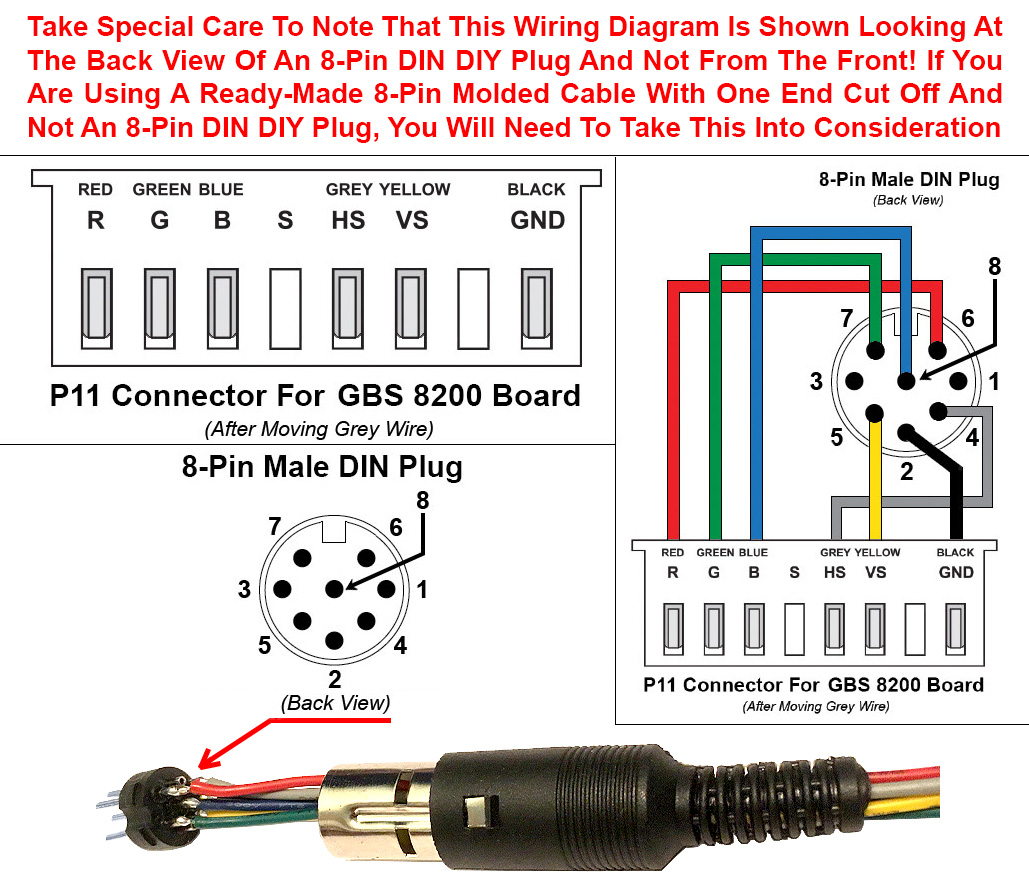
6 Pin Din Connector Wiring Diagram Wiring Din Wire Connect A 6 pin mini din wiring diagram is basically the same as a standard electric wiring diagram it shows how to connect a range of electrical wires and cables to work together. the difference is that a 6 pin mini din wiring diagram uses mini din plugs and sockets for connection to electrical equipment. it is especially useful for applications. The 6 pin mini din plug and connector are also commonly known as “ps 2” connectors when used for keyboard and mouse connections on computers. (this connector was first widely used on the ibm ps 2 family of personal computers in the mid to late 1980s. it has continued to be used for this purpose industry wide, until usb interfaced mice and. Exploring the many wiring diagrams of din connectors on the internet (an example shown in the image below), i note that the more detailed authors always emphasize whether one is looking at these connectors from the front (i.e. looking directly at the pins) or from the back (basically looking over the cable). The 6 pin mini din "data" or "packet" connector is an industry standard adopted by all the japanese ham radio manufacturers. it is now superseding the various proprietary 7, 8 and 13 pin full sized din connectors used by various manufacturers. this connector is the perfect point to connect packet tncs, soundcard interfaces, phone patches, irlp.

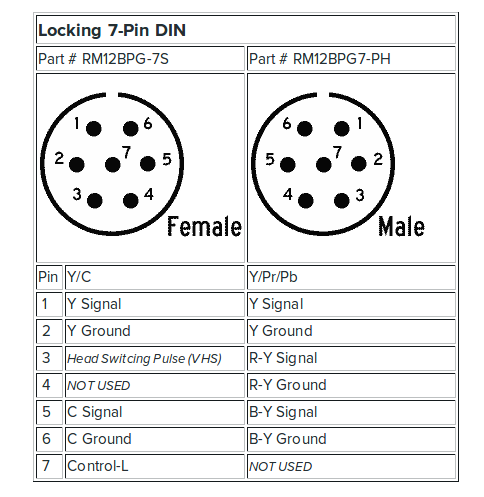
Kpc9612 Wiring Diagram 6 Pin Din Exploring the many wiring diagrams of din connectors on the internet (an example shown in the image below), i note that the more detailed authors always emphasize whether one is looking at these connectors from the front (i.e. looking directly at the pins) or from the back (basically looking over the cable). The 6 pin mini din "data" or "packet" connector is an industry standard adopted by all the japanese ham radio manufacturers. it is now superseding the various proprietary 7, 8 and 13 pin full sized din connectors used by various manufacturers. this connector is the perfect point to connect packet tncs, soundcard interfaces, phone patches, irlp. The wiring diagram for a 6 pin connector shows the pin configuration and the corresponding functions of each pin. the 6 pin connector can be found in a variety of applications, including automotive, computer, and industrial equipment. each pin has a specific purpose, such as transmitting power, ground, data signals, or control signals. There are two types of the 6 pin, the seven pin (with the outer pins forming either 360 0 or 300 0) and the eight pin (which has the outer pins at either 262 0 or 270 0). however, there are some limits to compatibility. for instance, a 3 pin connector can connect to an 180 0 5 pin socket using only 3 of the pins and not using the remaining two.

Diagram 4 Pin Din Schematic Diagram Wiring Mydiagram Online The wiring diagram for a 6 pin connector shows the pin configuration and the corresponding functions of each pin. the 6 pin connector can be found in a variety of applications, including automotive, computer, and industrial equipment. each pin has a specific purpose, such as transmitting power, ground, data signals, or control signals. There are two types of the 6 pin, the seven pin (with the outer pins forming either 360 0 or 300 0) and the eight pin (which has the outer pins at either 262 0 or 270 0). however, there are some limits to compatibility. for instance, a 3 pin connector can connect to an 180 0 5 pin socket using only 3 of the pins and not using the remaining two.

Comments are closed.