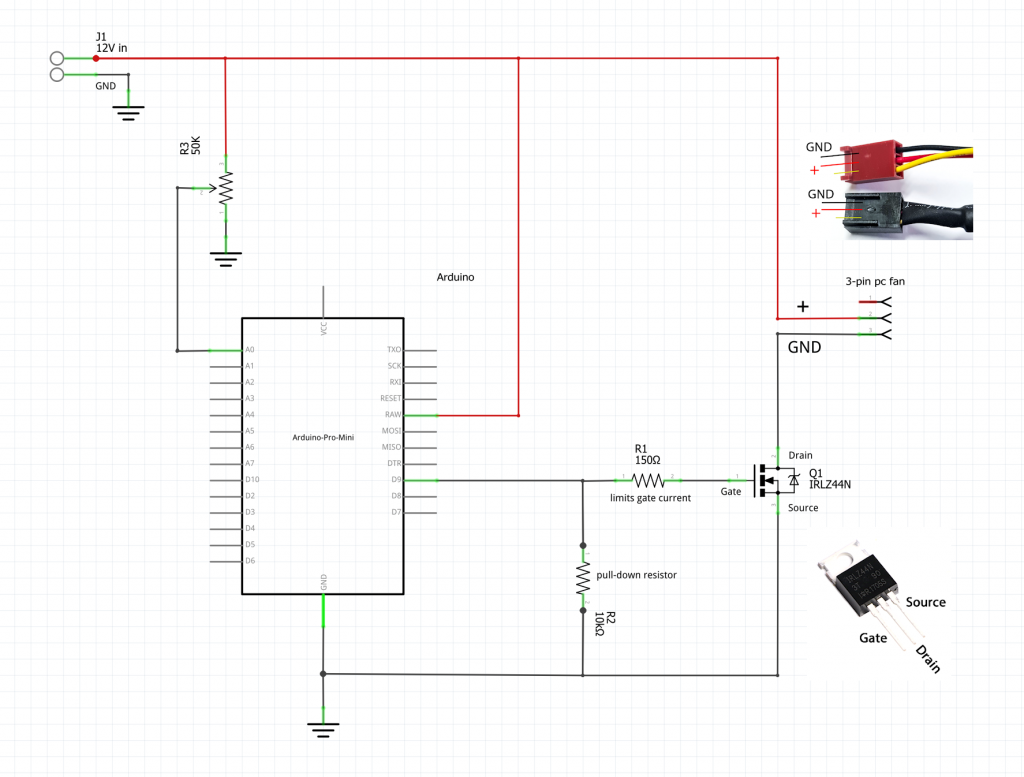
Diy Arduino Pwm Pc Fan Controller Part 1 Prototype 00 Vrogue Co

Diy Arduino Pwm Pc Fan Controller Part 1 Prototype 00 Vrogue Co Tl;dr:6:23 is where i start the demo7:44 is where i show current draw9:29 is where i go over the codei built a new pc, and noticed that half of the fans aren. Control the speed of a pc fan by pwm.

Diy Arduino Pwm Pc Fan Controller Part 1 Prototype 00 Vrogue Co My goal was to build a compact stand alone pwm fan controller to: monitor ambient temperature. turn on two 120mm 4 pin computer fans at a pre defined threshold. adjust the rpm according to. Nano fan controller. i made a simple fan controller to put in a computer case, powered directly from one of the fan headers on the motherboard. this controls up to 3 fans to keep the temperature inside the case in check. additional reading on arudino timers and pwm. secrets of arduino pwm; arduino timer and interrupt tutorial on oscarliang. Step 3: upload the code into the arduino. open the attached file with the arduino ide, connect the arduino to any usb port of your computer and upload the code. the way the code works is that it makes the arduino generate a pwm signal on pin 11 with a 25 khz frecuency and a certain duty cycle, the reason for a 25 khz signal is because it. Control the speed of your pwm fan easily. no need for other circuits. download this file and run it under the arduino ide. 1 const byte oc1a pin = 9;.

Diy Arduino Pwm Pc Fan Controller Part 1 Prototype 00 Vrogue Co Step 3: upload the code into the arduino. open the attached file with the arduino ide, connect the arduino to any usb port of your computer and upload the code. the way the code works is that it makes the arduino generate a pwm signal on pin 11 with a 25 khz frecuency and a certain duty cycle, the reason for a 25 khz signal is because it. Control the speed of your pwm fan easily. no need for other circuits. download this file and run it under the arduino ide. 1 const byte oc1a pin = 9;. Create a non blocking rpm measurement (with millis ()) this post addresses all three issues regarding how to pwm a 3 pin pc fan with an arduino. 1. you need a pnp transistor. most tutorials show an npn transistor driving a motor as a low side switch. however, the problem with this approach is that you are switching the ground (gnd) path. Use the first device to generate the input signals to read. then figure out how to read two signals concurrently. 3)write production code that samples two pwm input signals and produces a third with a duty cycle of std::min (100, in 1 in 2). hook that output up to the fan and debug things.

Diy Arduino Pwm Pc Fan Controller Part 1 Prototype 00 Vrogue Co Create a non blocking rpm measurement (with millis ()) this post addresses all three issues regarding how to pwm a 3 pin pc fan with an arduino. 1. you need a pnp transistor. most tutorials show an npn transistor driving a motor as a low side switch. however, the problem with this approach is that you are switching the ground (gnd) path. Use the first device to generate the input signals to read. then figure out how to read two signals concurrently. 3)write production code that samples two pwm input signals and produces a third with a duty cycle of std::min (100, in 1 in 2). hook that output up to the fan and debug things.

Comments are closed.