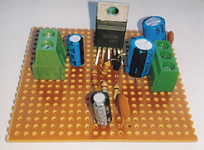
Diy Simple Powerful Amplifier Using Tda2030 Homemade Amplifier 12v

Diy Simple Powerful Amplifier Using Tda2030 Homemade Amplifier 12v Diy simple powerful amplifier using tda2030, homemade amplifier 12v. ( diy simple powerful amplifier )amplifier using tda2050 : youtu.be 2phgkvoevwkt. The functioning of this audio amplifier 12v using tda2030 is actually fairly easy. first, we’ll provide a 12v dc power source. when an audio input device, such as a smartphone or a microphone, is utilized, it then sent the audio input through a 2.2uf coupling capacitor. a coupling capacitor effectively blocks the dc component of the input.

14 Watt Hi Fi Audio Amplifier Using Tda2030a Full Diy Project Step 2: circuit diagram and working. · tda2030 ic had 5 pins, 1st pin non inverting, 2nd pin inverting, 3rd ve negative power pin, 4th output pin, and 5th ve positive power pin. · this is a single power supply circuit based circuit, so the 3rd and 5th pin are connected to the power supply 12 volt dc. when we connect our input signal towards. Tda2030 simple powerful amplifier, homemade 12v amplifier.hello friends in this video i will show you how to make a simple amplifier circuit at home. homemad. Step 10: connect power supply. now we connect a power supply adapter with the amplifier circuit. we are using dc 12v (3 amp) power supply with the amplifier circuit. connect 12v positive cable with 5no leg and negative cable with 3no leg of tda2030 sound ic. it is the time to connect sound ic with heat sink. The five tda2030 leads are categorized as two groups to be connected with amplifier circuit. group 1: pin 3 ( v power supply), pin 5 ( v power supply) group 2: pin 1 (non inverting audio input), pin 4 (audio out), pin 2 (inverting audio input) you will see later why tda2030 leads are categorized as two parts.

Powerful Amplifier Using Tda2030 Ic Mini Amplifier Diy 12v Step 10: connect power supply. now we connect a power supply adapter with the amplifier circuit. we are using dc 12v (3 amp) power supply with the amplifier circuit. connect 12v positive cable with 5no leg and negative cable with 3no leg of tda2030 sound ic. it is the time to connect sound ic with heat sink. The five tda2030 leads are categorized as two groups to be connected with amplifier circuit. group 1: pin 3 ( v power supply), pin 5 ( v power supply) group 2: pin 1 (non inverting audio input), pin 4 (audio out), pin 2 (inverting audio input) you will see later why tda2030 leads are categorized as two parts. The operation of this audio amplifier circuit using tda2030 ic is actually quite simple. first, we are providing a 12v dc supply. you can use 6v to operate this circuit an audio input device, such as a smartphone or a microphone, is used. it then passed the audio input through a 47uf coupling capacitor. the circuit is effectively blocking the. Useful steps. 1) solder the tda2030 ic on the pcb board. 2) connect the heatsink with the ic. 3) solder the 1k resistors on the veroboard. 4) after that, solder the two 1n4007 diodes on the pcb board. 5) solder the 100uf and 47uf capacitors on the pcb board. 6) solder the dc power jack on the pcb board.

Diy Tda2030 Simple Powerful Amplifier Homemade 12v Ampl The operation of this audio amplifier circuit using tda2030 ic is actually quite simple. first, we are providing a 12v dc supply. you can use 6v to operate this circuit an audio input device, such as a smartphone or a microphone, is used. it then passed the audio input through a 47uf coupling capacitor. the circuit is effectively blocking the. Useful steps. 1) solder the tda2030 ic on the pcb board. 2) connect the heatsink with the ic. 3) solder the 1k resistors on the veroboard. 4) after that, solder the two 1n4007 diodes on the pcb board. 5) solder the 100uf and 47uf capacitors on the pcb board. 6) solder the dc power jack on the pcb board.

Comments are closed.