Dld Projects Digital Clock Using 4026 Counter Ic Youtube

Dld Projects Digital Clock Using 4026 Counter Ic Youtube Digital clock using logic gate ics.simulation on proteus 8 ponents used:1.ic 4026.2.555 timmer .3.resistors(47k,470,330).4.7 segment display with common c. Date: march 1, 2021main components:1. cd 4026be (6) the 4026 is a decade counter integrated circuit (ic) with decoded outputs for driving a common cathode s.

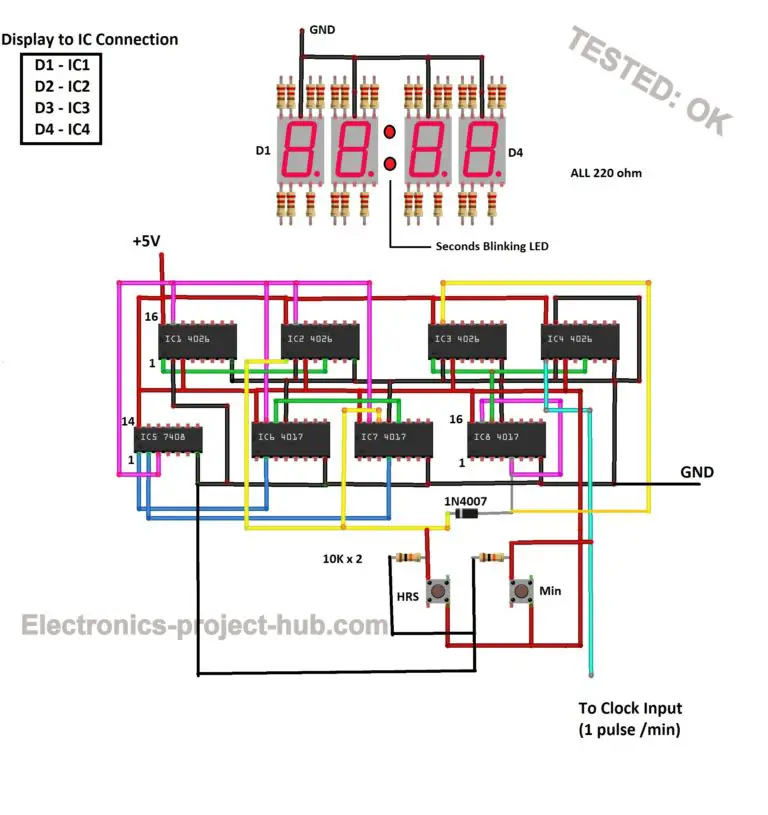
4026 Manual Digital Counter Circuit Diagram Welcome to my channel! in this video, i’ll show you how to build a diy digital clock using a 555 timer ic, 4026 decade counters, 7 segment displays, and a fe. All the circuit is power at 5v. note: the accuracy of this digital clock depends on how accurate you bring the ic 555 pulse to 1 hz. ic 4026 to 7 segment display connection: ic 4026 to 7 segment display connection. you need to connect the 220 ohm resistor to each segment as shown above. The two switch are used to set the time and is achieved using 4060 pin by increasing the frequency that is being fed to 4026 ic. the first switch which has lower frequency of the two is used to set the minutes in the clock. the second switch which has higher frequency is used to set the hours in the clock. 2. Place the clock circuit exactly below the seconds part of the digital clock, this will make connection easier between the ic 4026 and ic 555. at this point, it was completely useless to take pictures after each circuit, as the circuits get very complicated with lots of wires going around in different directions.

Digital Clock Circuit Diagram Using 7 Segment Display The two switch are used to set the time and is achieved using 4060 pin by increasing the frequency that is being fed to 4026 ic. the first switch which has lower frequency of the two is used to set the minutes in the clock. the second switch which has higher frequency is used to set the hours in the clock. 2. Place the clock circuit exactly below the seconds part of the digital clock, this will make connection easier between the ic 4026 and ic 555. at this point, it was completely useless to take pictures after each circuit, as the circuits get very complicated with lots of wires going around in different directions. This circuit diagram is for a seven segment display driven by a 4026 decade counter, which receives the clock signal from a 555 timer ic. if you made the previous circuit to this, which used a push to make (ptm) switch to generate a clock pulse, then this circuit is a step forward and uses a 555 ic in astable mode to generate a slow clock pulse. 0 – 99 counter using ic 4026. by anjali sethiya may 21, 2013. this circuit can be used in various projects where we require the counting. like in doctors’ clinic or hospitals, in restaurants, in customer care offices where long queue is there and we want to stop the rush at the counter. this system is very effective where man power is less.

Comments are closed.