Double Acting Pneumatic Cylinder Circuit Diagram

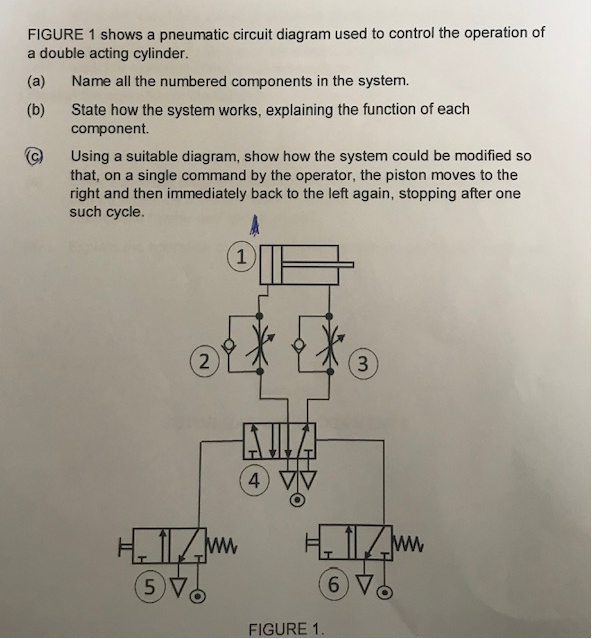
Solved Figure 1 Shows A Pneumatic Circuit Diagram Used To Chegg Create the circuit diagram: using symbols for the double acting cylinder and the directional control valve, create a circuit diagram that shows the flow of air through the system. connect the input and output ports of the cylinder to the appropriate ports on the control valve. add other components: if there are other components in the circuit. A double acting cylinder with a piston rod on both sides (fig.1.5) is a cylinder with a rod extending from both ends. this cylinder can be used in an application where work can be done by both ends of the cylinder, thereby making the cylinder more productive. double rod cylinders can withstand higher side loads because they have an extra.

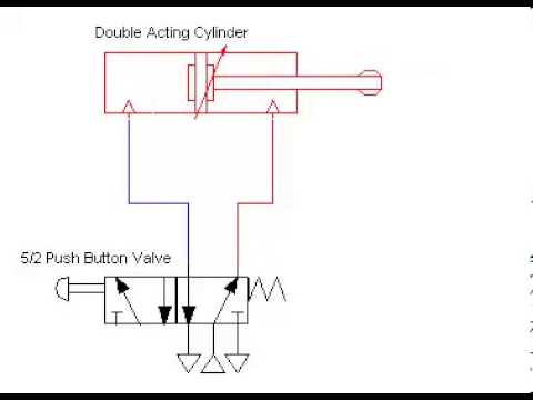
Draw A Pneumatic Circuit Diagram As a pneumatic actuator, a double acting pneumatic cylinder relies on compressed air to generate bidirectional force. whether extending or retracting, pneumatic cylinders convert energy found in compressed air into linear motion. note that single acting cylinders will exert force in only one direction, specifically extension. Double acting cylinder circuit automation to extend and retract an air cylinder is common in many machines. figure 3 shows a pneumatic circuit consisting of a 4 way solenoid valve (sol01) operating a double acting cylinder (cyl01). filtered air from the air preparation unit feeds a solenoid valve controlled by a plc. The 4 way, air piloted, directional control valve (vlv05) and the two 3 way roller actuated valves (vlv07and vlv08) are this circuit’s key pneumatic logic components. unlike electrical solenoids, they use air to control the 4 way valve’s spool position and are configured like limit switches with a mechanical arm. A double acting cylinder has no spring inside to return it to its original position. it needs two air supplies, one to outstroke the piston and the other to.

Machine Drawing Double Acting Cylinder Pneumatic Circuit The 4 way, air piloted, directional control valve (vlv05) and the two 3 way roller actuated valves (vlv07and vlv08) are this circuit’s key pneumatic logic components. unlike electrical solenoids, they use air to control the 4 way valve’s spool position and are configured like limit switches with a mechanical arm. A double acting cylinder has no spring inside to return it to its original position. it needs two air supplies, one to outstroke the piston and the other to. The diameter of the cylinder defines its force relative to the air pressure. the stroke tells us how many millimetres the piston and therefore the piston rod can travel. krämer kg, stammheimerstraße 10, d 70806 kornwestheim, germany, 0049 7154 178589 0, e mail: info@hafner pneumatik.de, web : hafner pneumatik . A typical pneumatic system configuration is shown in figure 4c. the theoretical force available in the actuator is the piston area multiplied by the supplied air pressure. spring force must be subtracted from this value for single acting cylinders. the actual force of the actuator will be 3 20 percent less due to pressure losses in the system.
Solved Draw A Pneumatic Circuit To Safely Control A Double Acting The diameter of the cylinder defines its force relative to the air pressure. the stroke tells us how many millimetres the piston and therefore the piston rod can travel. krämer kg, stammheimerstraße 10, d 70806 kornwestheim, germany, 0049 7154 178589 0, e mail: info@hafner pneumatik.de, web : hafner pneumatik . A typical pneumatic system configuration is shown in figure 4c. the theoretical force available in the actuator is the piston area multiplied by the supplied air pressure. spring force must be subtracted from this value for single acting cylinders. the actual force of the actuator will be 3 20 percent less due to pressure losses in the system.

Moving A Cylinder Java Chief Delphi

Comments are closed.