Dual Voltage 3 Phase Motor Wiring How To Wire A Multi Voltage ођ

Dual Voltage 3 Phase Motor Wiring How To Wire A Multiођ In this video, i will show you how to wire a dual voltage 3 phase motor for any type of application. stay tuned for new videos every week!a type of three pha. How dual voltage motors work, and how to wire them even without the wire labels. i have received several requests to cover this topic. if you want to chip in.

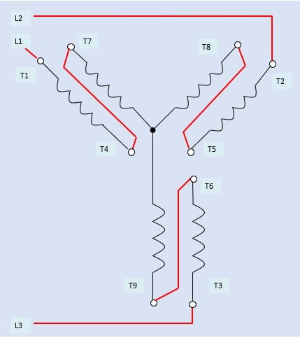
Three Phase Dual Voltage Motor Wiring вђ Middle Tn Rses 0. many 3 phase motors allow for two possible line voltages, for example 230 460. i am trying to understand how the different wiring is changing the way the windings get current. i would guess that wiring for high voltage the motor would use all the windings and when wiring for low voltage it would only utilize half the windings. Don't get overwhelmed with 3 phase! it's not that complicated! bryan is back with more of his knowledge this time on dual voltage and part start 3 phase moto. Nine wire three phase motors. the most common type of three phase motor is that which has nine labeled (and often colored) wires coming out of the box on the side. there are many motors with more or fewer wires, but nine is the most common. these nine wire motors may be internally connected with either a wye (star) or a delta configuration. The three main components of a 3 phase wiring diagram for motors are: power supply: the diagram shows the three phase power supply, typically labeled as l1, l2, and l3. these represent the three separate phases of the power source. motor: the diagram illustrates the motor as a single unit with labeled terminals.

3 Phase Motor Wiring Installation Wiring Diagram And Schematics Nine wire three phase motors. the most common type of three phase motor is that which has nine labeled (and often colored) wires coming out of the box on the side. there are many motors with more or fewer wires, but nine is the most common. these nine wire motors may be internally connected with either a wye (star) or a delta configuration. The three main components of a 3 phase wiring diagram for motors are: power supply: the diagram shows the three phase power supply, typically labeled as l1, l2, and l3. these represent the three separate phases of the power source. motor: the diagram illustrates the motor as a single unit with labeled terminals. Supply line l3 must be connected common with motor terminal leads t3, t5 and t9. this completes the delta configuration within the 3 phase ac induction motor for 230 v operation. as a memory aid, the three common lines and motor terminal connections create the numbers: 1167, 2248 and 3359. Title: three phase motor connection diagram dual voltage author: inverter drive supermarket created date: 20130110120137z.

Comments are closed.