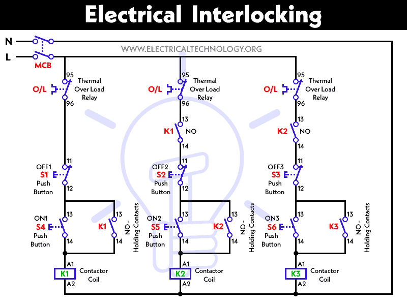
Electrical Interlocking System

What Is Electrical Interlocking Power And Control Diagrams What is electrical interlocking? power and control. Switchgear interlocking system and arc protection that you.

How To Interlocking In Electrical System Contactor Interlock Motor In this video, we will tackle about interlocking system between contactors of the control circuit in forward and reverse operation with a fully illustrated e. The interlock would prevent in case if the main power and the generator power from powering the electrical system at the same time. in case if there is no interlock if the main power comes online so both these two power sources would create an overload condition. Interlock (engineering). An electrical interlock circuit diagram typically consists of several interconnected components and switches. these components relay information about the state of the system to the interlock circuit, and the circuit then takes action based on this information. for example, if an overload is detected, the interlock circuit can either shut down.

What Is Electrical Interlocking Nationwide Fire Protection Denver Interlock (engineering). An electrical interlock circuit diagram typically consists of several interconnected components and switches. these components relay information about the state of the system to the interlock circuit, and the circuit then takes action based on this information. for example, if an overload is detected, the interlock circuit can either shut down. An interlock relay diagram is a visual representation of how an interlock relay operates. interlock relays are used in electrical systems to prevent the simultaneous operation of two or more circuits. they ensure that only one circuit can be energized at a time, which helps protect equipment and prevent accidents. In summary, an interlock is a method for restricting action. there are two main types of interlocks: – safe. – non safe. there are three types of interlocks: – mechanical, – electrical, – logical. each interlock has a specific use to help take control of a system and prevent undesirable actions.

Electrical Interlocking System Youtube An interlock relay diagram is a visual representation of how an interlock relay operates. interlock relays are used in electrical systems to prevent the simultaneous operation of two or more circuits. they ensure that only one circuit can be energized at a time, which helps protect equipment and prevent accidents. In summary, an interlock is a method for restricting action. there are two main types of interlocks: – safe. – non safe. there are three types of interlocks: – mechanical, – electrical, – logical. each interlock has a specific use to help take control of a system and prevent undesirable actions.

Comments are closed.