Electrical Interlocking Wiring Diagram Pdf Wiring Diagram And Schemati

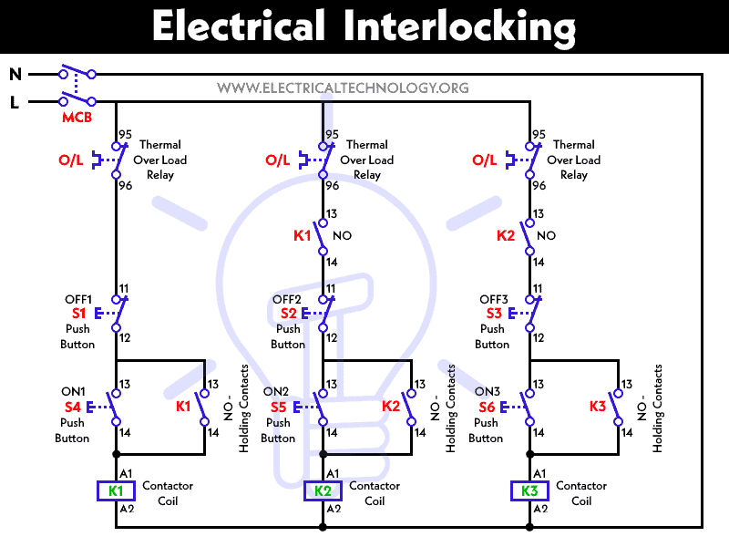
Electrical Interlocking Control Circuit Diagram What is electrical interlocking? power and control. An electrical interlock circuit diagram typically consists of several interconnected components and switches. these components relay information about the state of the system to the interlock circuit, and the circuit then takes action based on this information. for example, if an overload is detected, the interlock circuit can either shut down.

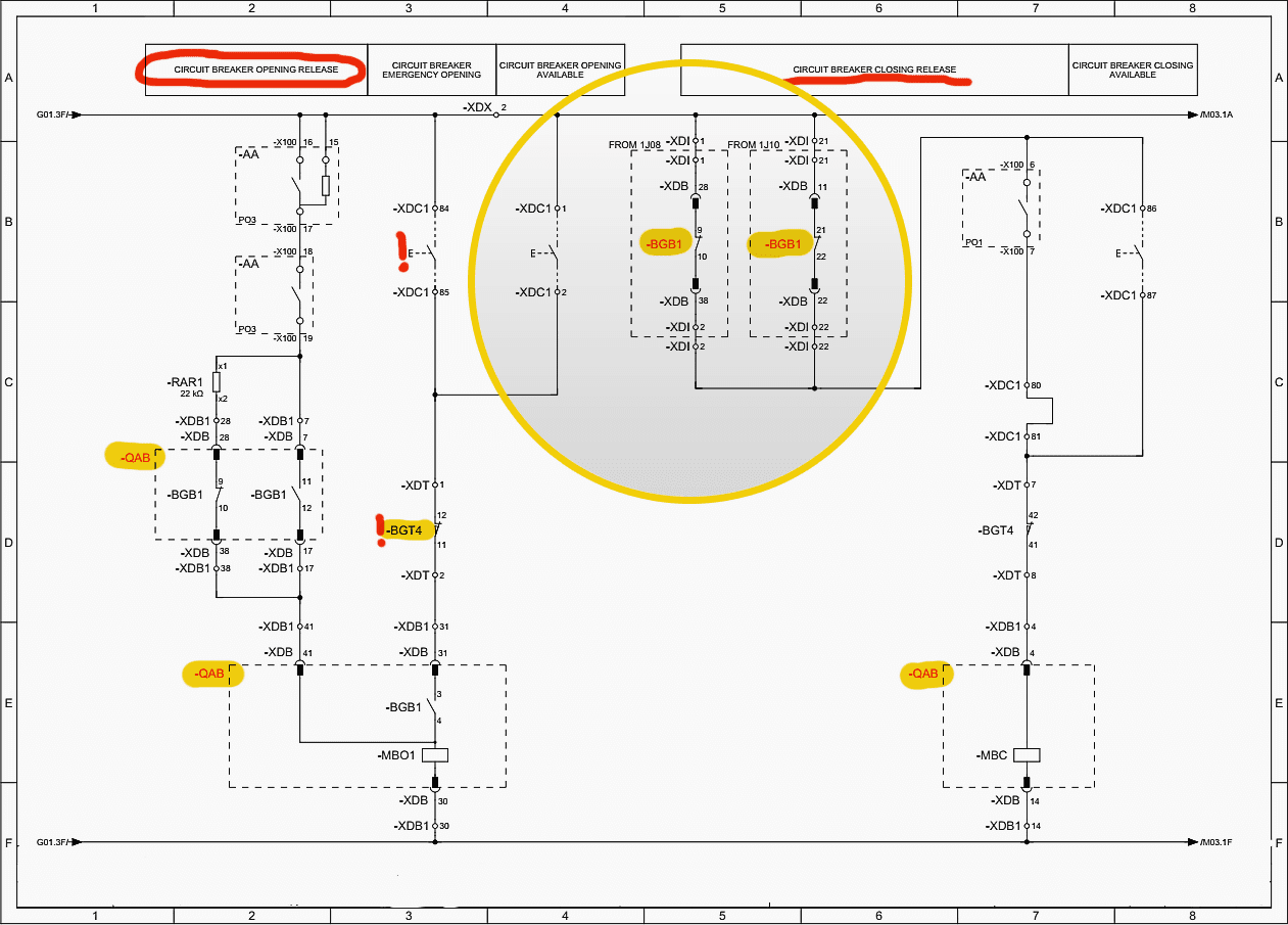
What Is Electrical Interlocking Power And Control Diagrams Download electrical ce interlocks wiring diagram manual, read through this diagram pdf to ensure proper use. if you are in any doubt share at parts@itscnc keywords: fadal electrical ce interlocks wiring diagram manual, wiring diagram manual pdf, electrical ce interlocks wiring diagram pdf, electrical ce interlocks wiring diagram. An interlock wiring diagram is a visual representation of how different electrical components in a system are connected and interact with each other. it shows the connections between relays, contacts, switches, and other devices to ensure proper sequencing and interlocking of various parts of the system. interlock wiring diagrams follow a. The symbols used in these diagrams show how individual components interact with one another, and which components are connected. to understand this, you’ll need to familiarize yourself with the different symbols used in interlocking schematics. common symbols include arrows, circles, squares, and triangles, and each one has a specific meaning. Required when a two wire control device is used. the bulletin 595 auxiliary contacts are designed as “a” and “b” on the wiring diagram. these contacts are easily. added to any allen bradley bulletin 500 starter sizes 0 through 4. when this system is used, the phase connections on all of the starters must be the same.

Electrical Interlocking Wiring Diagram Pdf Wiring Diagram The symbols used in these diagrams show how individual components interact with one another, and which components are connected. to understand this, you’ll need to familiarize yourself with the different symbols used in interlocking schematics. common symbols include arrows, circles, squares, and triangles, and each one has a specific meaning. Required when a two wire control device is used. the bulletin 595 auxiliary contacts are designed as “a” and “b” on the wiring diagram. these contacts are easily. added to any allen bradley bulletin 500 starter sizes 0 through 4. when this system is used, the phase connections on all of the starters must be the same. In the diagram below, you can see the basic elements of an electrical interlock circuit, including a magnetically operated switch, an actuator, a sensor, and a control unit. the diagram illustrates how the switch senses when a door is opened or closed, triggering the actuator to move the contacts in the circuit. The diagrams also provide information about different types of circuit connections and the power supply connections. using an electrical interlocking wiring diagram allows an electrician or engineer to install the right wiring for any type of electrical system. it can help ensure the safe operation of the system and prevent unexpected malfunction.

Interlock Single Line Diagram In the diagram below, you can see the basic elements of an electrical interlock circuit, including a magnetically operated switch, an actuator, a sensor, and a control unit. the diagram illustrates how the switch senses when a door is opened or closed, triggering the actuator to move the contacts in the circuit. The diagrams also provide information about different types of circuit connections and the power supply connections. using an electrical interlocking wiring diagram allows an electrician or engineer to install the right wiring for any type of electrical system. it can help ensure the safe operation of the system and prevent unexpected malfunction.

Comments are closed.