Ethernet Wiring Diagram Cat5e

Cat5e Cable Wiring Schemes вђ Red Lion Support Rj45 pinout for a crossover lan cable. pin 1 ← white and green wire → pin 3. pin 2 ← green wire → pin 6. pin 3 ← white and orange wire → pin 1. pin 4 ← blue wire → pin 4. pin 5 ← white and blue wire → pin 5. pin 6 ← orange wire → pin 2. pin 7 ← white and brown wire → pin 7. pin 8 ← brown wire → pin 8. Learn how to install cat 5e cables for fast and reliable network connections. find out the factors to consider when choosing the right cable, the tools and equipment needed, and the steps to follow for successful installation.

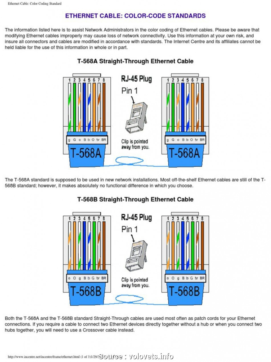
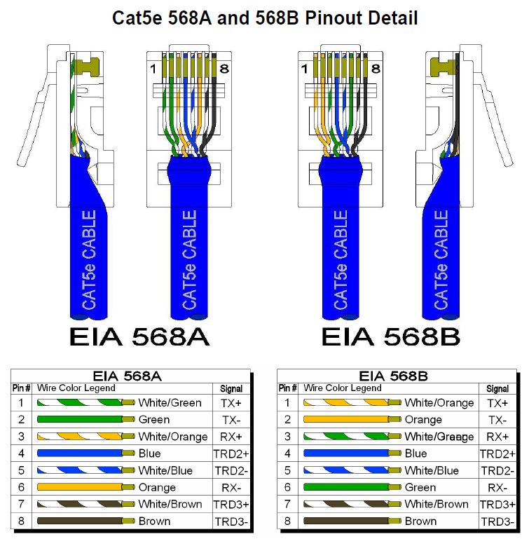
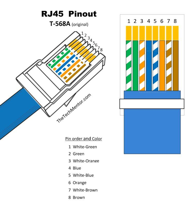
Ethernet Wiring Diagram Cat5e Crossover cat5e wiring diagram. crossover cables can connect a computer’s ethernet card to another without any networking equipment. inside the cable, the wires connect the transmit (tx) pins directly to the receive (rx) pins and vice versa, in a cross fashion and hence the name. most of the latest network cards are auto sensing. The most commonly used form of cat5 cable is cat5e cable which supports the network bandwidth of up to 100mhz. the cable transfers data with the speed of 1000 base t, i.e., gigabit ethernet speed. these are the cables commonly used in large data centers, computer networking offices, and homes. The wiring diagram outlines how the eight pins in the connector are used for transmitting and receiving data. one popular type of wiring diagram is for category 5e (cat 5e) cables, which are commonly used in ethernet networks. the cat 5e wiring diagram shows the arrangement of the four twisted pairs of wires inside the ethernet cable. Cat5e wiring diagram and methods. each pair of copper wires in the cat5e has insulation with a specific color for easier identification. cat5e wiring should follow the standard color code. for the straight through wiring method, there are two standards recognized by ansi, tia and eia: t568a and t568b. both of them can be used.

Cat5e Ethernet Cables Advantech The wiring diagram outlines how the eight pins in the connector are used for transmitting and receiving data. one popular type of wiring diagram is for category 5e (cat 5e) cables, which are commonly used in ethernet networks. the cat 5e wiring diagram shows the arrangement of the four twisted pairs of wires inside the ethernet cable. Cat5e wiring diagram and methods. each pair of copper wires in the cat5e has insulation with a specific color for easier identification. cat5e wiring should follow the standard color code. for the straight through wiring method, there are two standards recognized by ansi, tia and eia: t568a and t568b. both of them can be used. The cat5e cable has eight wires twisted into four pairs. each wire carries a specific signal, and the correct arrangement of these wires is crucial for proper connectivity. the pinout diagram for a cat5e cable shows the following wire connections: pin 1: white orange wire. pin 2: orange wire. pin 3: white green wire. Step 2: cut and strip the cable ends. use your wire cutters to cut both ends of the cat5 cable to the desired length. leave a little extra length to work with. then, use the wire strippers to remove 1 to 1.5 inches of the outer sheath jacket from both ends, exposing the 4 internal wire pairs.

Ethernet Wiring Diagram Cat5e The cat5e cable has eight wires twisted into four pairs. each wire carries a specific signal, and the correct arrangement of these wires is crucial for proper connectivity. the pinout diagram for a cat5e cable shows the following wire connections: pin 1: white orange wire. pin 2: orange wire. pin 3: white green wire. Step 2: cut and strip the cable ends. use your wire cutters to cut both ends of the cat5 cable to the desired length. leave a little extra length to work with. then, use the wire strippers to remove 1 to 1.5 inches of the outer sheath jacket from both ends, exposing the 4 internal wire pairs.

Comments are closed.