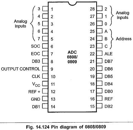
Explain The Pin Diagram Of Adc 0808 0809 And Method Of Int

Pin Diagram Adc 0808 0809 а а їа ёаґќа аґђ Youtube Adc0808 pin diagram | features | operation | interfacing. This requires hardware and necessary software, resulting in increased complexity and hence the total cost. the circuit of a to d converter shown here is configured around adc 0808, avoiding the use of a microprocessor. the adc 0808 is an 8 bit a to d converter, having data lines d0 d7. it works on the principle of successive approximation.

Adc0808 Pin Diagram Features Operation Interfacing The adc0808 ic is a commonly used adc module for projects were an external adc is required. it is a 28 pin eight channel 8 bit adc module. meaning it can measure up to eight adc value from 0v to 5v and the precision when voltage reference (vref –pin 9) is 5v is 19.53mv (step size). that is for every increase of 19.53mv on input side there. 06: explain the pin diagram of adc 0808 0809 and method of interfacing to 8086 microprocessor with suitable example. your solution’s ready to go! our expert help has broken down your problem into an easy to learn solution you can count on. Pin is a function of the binary numbers at the do – d7 inputs of the dac0808 and the reference current (i re f), and is as follows: q.2 explain pic18f458 adc with features. adc is analog to digital converter. it converts voltage into corresponding digital value. adc used in data acquisition system. The adc0808, adc0809 data acquisition component is a monolithic cmos device with an 8 bit analog to digital converter, 8 channel multiplexer and microprocessor compatible control logic. the 8 bit a d converter uses successive approximation as the conversion technique. the converter features a high impedance chopper stabilized comparator, a 256r.

Draw Adc Block Diagram And Explain Pin is a function of the binary numbers at the do – d7 inputs of the dac0808 and the reference current (i re f), and is as follows: q.2 explain pic18f458 adc with features. adc is analog to digital converter. it converts voltage into corresponding digital value. adc used in data acquisition system. The adc0808, adc0809 data acquisition component is a monolithic cmos device with an 8 bit analog to digital converter, 8 channel multiplexer and microprocessor compatible control logic. the 8 bit a d converter uses successive approximation as the conversion technique. the converter features a high impedance chopper stabilized comparator, a 256r. The adc0808 adc0809 is an 8 bit adc that also contains an 8 channel multiplexer. the fpga used in this case was the altera 10k20rc240 4 that is found on the up 1 boards used in the course. the purpose of this documentation is to first introduce users to the adc0808 adc0809, then to outline how to connect external circuitry to the adc, and then. Adc (analog to digital converter), interface with 8086, soc start of conversion, eoc end of conversion, adc 0808 0809, block diagram, pin diagram, successive approximation adc, timing diagram, adc 0804, dac0830 block diagram, pin diagram, successive approximation adc, timing diagram, adc 0804, dac0830, r 2r ladder, r 2r ladder dac.

Comments are closed.