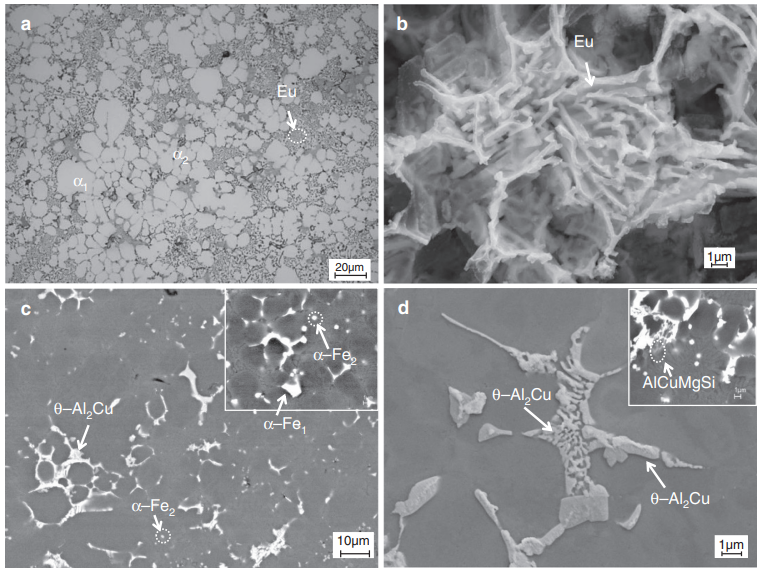
Fig 1 The As Cast Microstructure Of The Alвђ Siвђ Cu Alloy Containing 0 1

Fig 1 The As Cast Microstructure Of The Alвђ Siвђ Cu Al 3.2 grain structure of al–zn–mg–cu–sc–zr alloy ingot. the as cast microstructure of sc free and sc containing alloys is shown in fig. 2. the typical grain structure of sc free (alloy 1) consists of large columnar grains with a dendritic substructure, as shown in fig. 2a, b. the average grain size is measured to be about 100 μm. Wang shao hua, et al trans. nonferrous met. soc. china 21(2011) 1449−1454 1452 fig. 5 bei (a) and elements cu (b) and er (c) mapping analyses of homogenized alloy 2 4 discussion 4.1 as cast microstructure in the al zn mg cu alloy, η(mgzn 2 ) phase is thought to be the predominant phase under as cast condition.

Fig1 Microstructure Of As Cast And Homogenized Alloy Download 3 results and discussion 3.1 as cast microstructure figure 1 shows the microstructure of the as cast alloy. the results of edx analysis are listed in table 1. it can be seen that a large number of residual phases exist at the grain boundaries. these phases in fig. 1(b) show different shapes with different contrast. Fig. 1. curves of phases changing with temperature in al–zn–mg–cu alloy: a 7056 alloy, b 7095 alloy, and c 7136 alloy. full size image. xrd patterns are shown in fig. 2. it clearly can be seen that all of these three alloys consist of α (al) and η (mgzn 2) phases. figure 3 shows the om images of as cast alloys. Figure 9 shows the relationships between γ and the minimum grain size d min for the intensely drawn cu alloy wires fabricated using the same deformation conditions in conjunction with the data of cu–(1.0, 2.5, and 4.0) at. pct in alloy wires reported previously and those of cu–zn and cu–al alloys prepared using ecap and hpt methods. After solution treatment, the cu containing phases of the 2cu and 3cu alloys almost dissolve into the al matrix (fig. 3 (c) and (d)), and a small amount of residual cu containing phases distribute on the grain boundary, identified as the θ al 2 cu and q alcumgsi phases based on eds analysis of the 3cu alloy (refer to fig. 3 (e) and (f)).

Comments are closed.