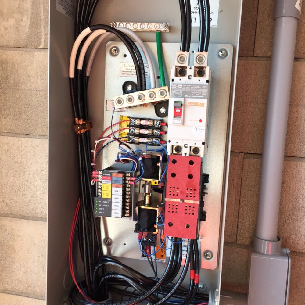
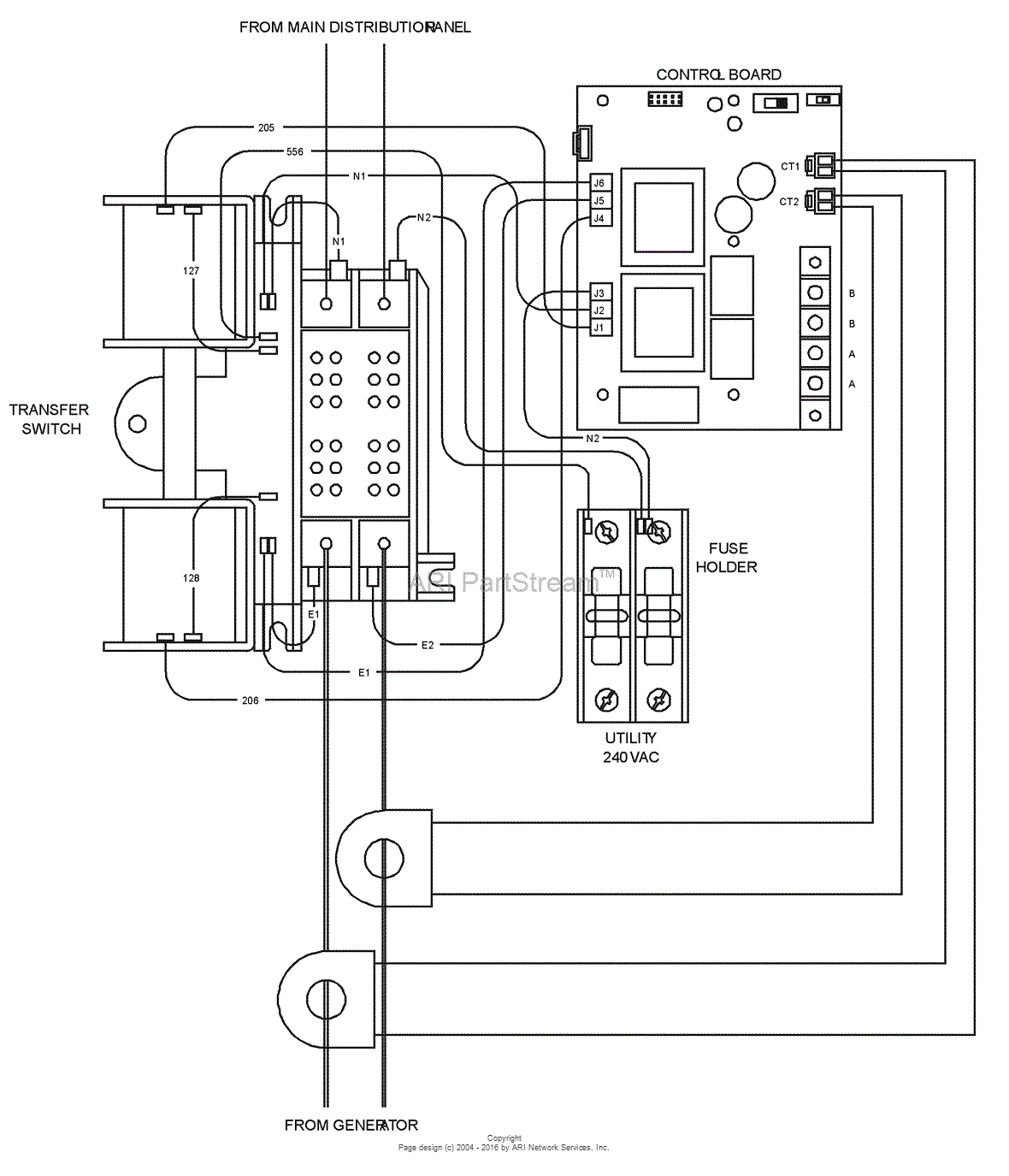
Generac Automatic Transfer Switch Wiring

Generac 200 Amp Automatic Transfer Switch Wiring Diagram Owner's manual automatic transfer switch. With an accurate ac voltmeter and frequency meter, check the no load, voltage and frequency. measure across ats terminal lugs e1 to e2, e2 to e3 and e1 to e3. neutral and e3 to neutral. it will also be necessary to verify that the phase rotation of the util ity matches the phase rotation of the generator.

Generac Automatic Transfer Switch Wiring If the switch is to be mounted indoors, the wiring can enter the switch on any side (top, bottom, sides), national and local codes shall be followed. for transfer switches installed outdoors, the wiring can enter the switch from the top side but must use fittings listed for use in wet locations as required by article 312.2 of the national. This ul listed transfer switch is for use in optional standby systems only (nec article 702). this transfer switch is suitable for use on a circuit capable of 22,000 rms symmetrical amperes, 240 vac maximum. figure 2 1. typical single phase ats transfer mechanism switch rating wire range conductor torque specification 300 400a (1) #4 600 mcm. Automatic transfer switch the commercial transfer switch range (tx) is designed to operate independently with any standard generator utiliz ing 2 wire start. the transfer switch is programmed locally using the integrated display and touchpad. the tx switch controller dictates all operation of transfer switch operation, generator function, and. The system is now ready for automatic operation. 6. turn off the utility power supply to the transfer switch. with the generator ready for automatic operation, the engine should crank and start when the utility source power is turned off after a 10 second delay (factory default setting).

Generac Automatic Transfer Switch Wiring Diagram Automatic transfer switch the commercial transfer switch range (tx) is designed to operate independently with any standard generator utiliz ing 2 wire start. the transfer switch is programmed locally using the integrated display and touchpad. the tx switch controller dictates all operation of transfer switch operation, generator function, and. The system is now ready for automatic operation. 6. turn off the utility power supply to the transfer switch. with the generator ready for automatic operation, the engine should crank and start when the utility source power is turned off after a 10 second delay (factory default setting). How does an automatic transfer switch work?. To control an air • when an automatic transfer switch is installed for a standby conditioner, no additional equipment is required. internal relays generator set, the generator engine may crank and start at interrupt the thermostat 24vac control signal to disable the air any time without warning.

Comments are closed.