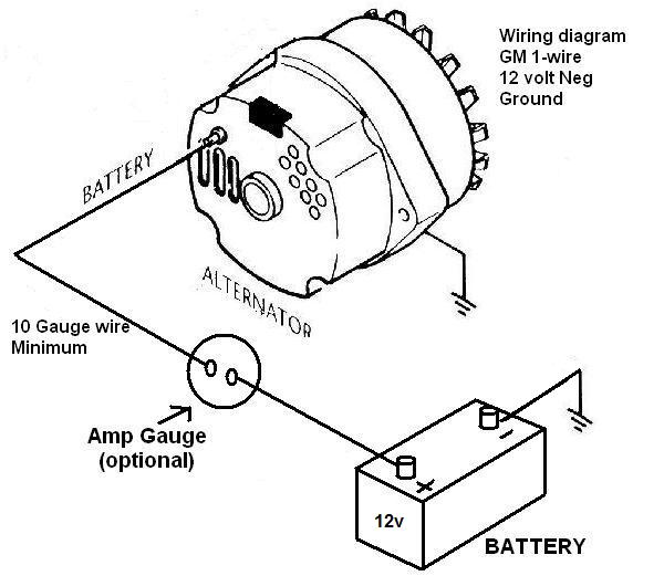
Gm Alternator Wiring Diagram 1 Wire

1 Wire Gm Alternator Diagram Step 6: reconnect the negative terminal of the battery. once all connections have been made, reconnect the negative terminal of the battery. check all wiring connections to ensure they are secure and properly insulated. following these steps will allow you to wire a 1 wire gm alternator successfully. 1 wire alternators require only 1 wire to operate. simply run one wire from the alternator ‘battery’ terminal to the positive terminal of the battery or to the starter solenoid main lug, which is connected to the positive battery post. make sure that the battery is fully charged. reconnect the ground cable, start the engine and using a vom.

Gm One Wire Alternator Wiring Diagram Alternator rating wire size available kits 75 amps 10 gauge high output alternator wiring kit 555 10510 100 amps 8 gauge 150 amps 6 gauge 200 amps 4 gauge it is very important to use the correct wire size to connect the alternator to the battery. a wire size too small can allow the wire to overheat, melt the insulation and cause a fire or. To begin the wiring process, locate the two main terminals on the alternator. one terminal is labeled “batt” or “bat,” while the other is labeled “2” or “fld.”. connect a heavy gauge wire from the batt bat terminal to the positive side of the vehicle’s battery. this wire will serve as the main power feed for the alternator. Make sure there is enough clearance for the alternator to function properly. step 3: connect the single wire from the gm alternator to the positive terminal of the battery. use a ring terminal and a wire crimper to securely attach the wire to the terminal. make sure the connection is tight and free of any corrosion. So if your alternator housing is unmarked, look from the rear of the alternator: the #1 terminal is on the left and the #2 on the right. you only need an ignition wire to the #1 terminal to make an si series alternator work. the #2 terminal is for voltage sensing, and is optional. the #2 voltage sensing terminal allows the voltage regulator to.

Comments are closed.