Guide To Understand Hydraulic Cylinder Parts Names Diagram

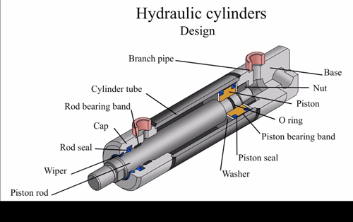
Hydraulic Cylinder Guide Identifying Parts Of Hydraulic Cylinders Its design is simple, and it is the same from an early age. let’s look at all the parts of the hydraulic cylinder, including their names and diagrams. parts of a hydraulic cylinder. cylinder barrel. base. cylinder head end cap. piston. piston rod. seal gland. The first major part of a hydraulic cylinder is the barrel, which is a smooth cylinder that keeps pressure inside the cylinder. designed internally to reach the correct diameter, most cylinder barrels have exterior finishes between four and 16 micrometers. additionally, there are two major types of barrels: single acting and double acting.

Guide To Understand Hydraulic Cylinder Parts Names Diagram Hydraulic cylinders transform the pressure and oil flow in a hydraulic system into work or mechanical force. they are used where linear motion is required to move something. also known as ‘hydraulic jacks’, ‘hydraulic rams’ or ‘actuators’, they convert fluid power into mechanical energy. a hydraulic cylinder differs from a hydraulic. Leak stoppers: seals and rings are the unsung heroes of hydraulic cylinders. their primary function is to prevent hydraulic fluid from escaping the system, maintaining the pressure needed for effective operation. shape matters: seals come in a variety of shapes to suit different parts of the cylinder, including: o rings: these versatile, round. A hydraulic cylinder schematic diagram is a visual representation of a hydraulic cylinder system. it shows the various components and the flow of hydraulic fluid within the system, helping to understand how the cylinder functions and operates. the schematic diagram typically includes symbols for the different components, such as the cylinder. Series 2an cylinders piston seal kits 46 47 rod seal kits 48 49 ts 2000 seal kits and gland replacement procedure 50 51 series 3h large bore hydraulic cylinders parts identification 52 53 seal kits 53 series 3h 7" & 8" bore hydraulic cylinders parts identification and maintenance instructions 54 & 55 series hmi cylinders parts identification 56 57.

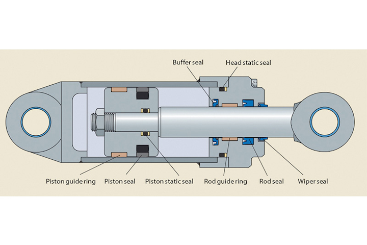
Hydraulic Cylinder Repair Companies Near Me It Feels Right Bloggers A hydraulic cylinder schematic diagram is a visual representation of a hydraulic cylinder system. it shows the various components and the flow of hydraulic fluid within the system, helping to understand how the cylinder functions and operates. the schematic diagram typically includes symbols for the different components, such as the cylinder. Series 2an cylinders piston seal kits 46 47 rod seal kits 48 49 ts 2000 seal kits and gland replacement procedure 50 51 series 3h large bore hydraulic cylinders parts identification 52 53 seal kits 53 series 3h 7" & 8" bore hydraulic cylinders parts identification and maintenance instructions 54 & 55 series hmi cylinders parts identification 56 57. A hydraulic cylinder has eight basic components; the clevis, gland, port (s), barrel, rod, piston, the end cap, and the seal. when combined, these parts allow the hydraulic cylinder to pressurise fluid that mobilises a piston to generate power for a machine. hydraulic cylinders and rams power most of our machinery, but the core design is more. This video is part one of a two part series that dives deeper into the world of hydraulic cylinders. in this, the first part, we'll be providing an overview.

Sealing The Deal In Hydraulic Cylinders Pi Process Instrumentation A hydraulic cylinder has eight basic components; the clevis, gland, port (s), barrel, rod, piston, the end cap, and the seal. when combined, these parts allow the hydraulic cylinder to pressurise fluid that mobilises a piston to generate power for a machine. hydraulic cylinders and rams power most of our machinery, but the core design is more. This video is part one of a two part series that dives deeper into the world of hydraulic cylinders. in this, the first part, we'll be providing an overview.

Comments are closed.