How Pwm Pulse Width Modulation Works With Arduino 1 Article To

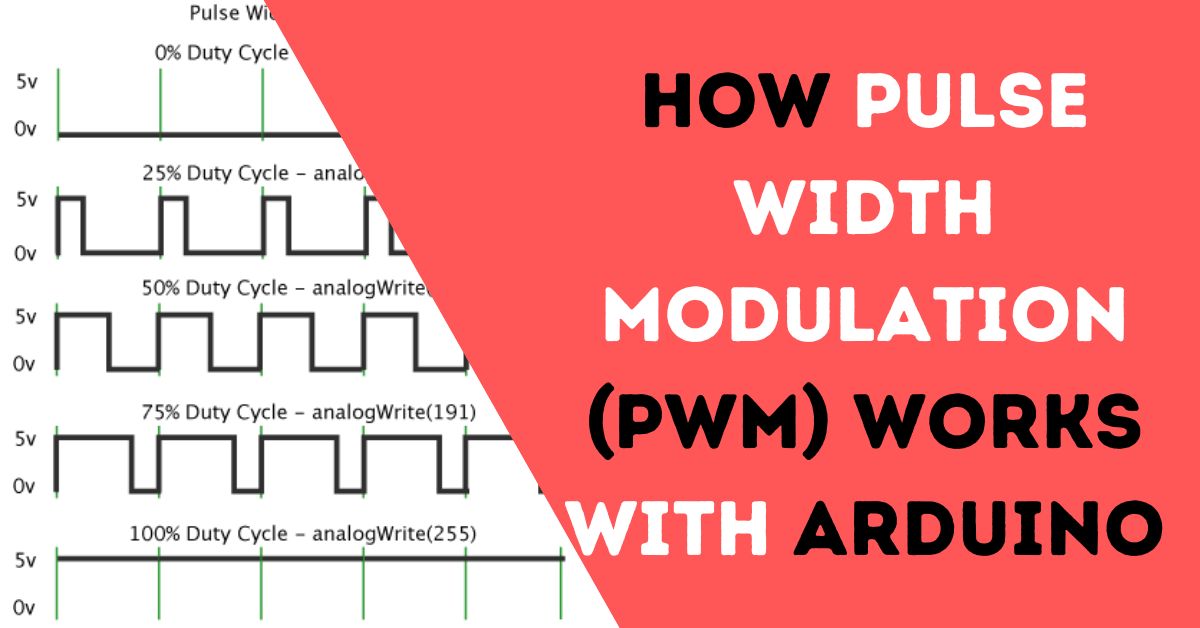
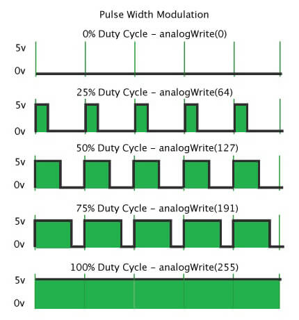
How Pwm Pulse Width Modulation Works With Arduino 1 Article To Pulse width modulation. a pulse width modulation signal is made up of short, high frequency pulses of current. the signal looks like a square wave, with the voltage switching from 5 volts to 0 volts very quickly: on the arduino, the pulse width modulation frequency is around 500 hz, so there are 500 of these cycles happening every second. Pulse width modulation, or pwm, is a technique for getting analog results with digital means. digital control is used to create a square wave, a signal switched between on and off. this on off pattern can simulate voltages in between the full vcc of the board (e.g., 5 v on uno, 3.3 v on a mkr board) and off (0 volts) by changing the portion of the time the signal spends on versus the time that.

Basics Of Arduino Pwm Pulse Width Modulation Circuit Geeks Pulse width modulation (pwm) can be implemented on the arduino in several ways. this article explains simple pwm techniques, as well as how to use the pwm registers directly for more control over the duty cycle and frequency. this article focuses on the arduino diecimila and duemilanove models, which use the atmega168 or atmega328. Using pwm in your sketch. add pwm output to your sketch using the analogwrite () function. here’s a basic example: pinmode(ledpin, output); sets the pin as output. void loop() {. val = analogread(analogpin); read the input pin analogwrite(ledpin, val 4); analogread values go from 0 to 1023, analogwrite values from 0 to 255. Understanding the basics of pulse width modulation (pwm). Step 2b: setting up a simple pwm circuit. in this step, i will be showing how to build the circuit for this project. start by connecting the shorter ve leg (called cathode) of the led to any gnd pin on the arduino and the longer ve leg (called anode) to any pwm capable pin.

Arduino Pwm Pulse Width Modulation Youtube Understanding the basics of pulse width modulation (pwm). Step 2b: setting up a simple pwm circuit. in this step, i will be showing how to build the circuit for this project. start by connecting the shorter ve leg (called cathode) of the led to any gnd pin on the arduino and the longer ve leg (called anode) to any pwm capable pin. Pulse width modulation or pwm, is a technique to generate an analog like signal within a digital pin. arduino digital pins generally use a square wave to control things. so it has only two states, high (5 v on uno, 3.3 v on an mkr board) and low (0 volts). in the pwm technique, a square wave is switched between on and off state at high frequency. We can use two characteristics to describe an arduino pwm (or any pwm) signal: 1. frequency: how often pulses occur in a given period of time. 2. duty cycle: what percentage of time the signal is on. a 50% duty cycle signal, for instance, would have the same repeating on time and off time. frequency tends to stay constant in a control signal.

Pwm Working Principle Pulse Width Modulation How It Works Motor Pulse width modulation or pwm, is a technique to generate an analog like signal within a digital pin. arduino digital pins generally use a square wave to control things. so it has only two states, high (5 v on uno, 3.3 v on an mkr board) and low (0 volts). in the pwm technique, a square wave is switched between on and off state at high frequency. We can use two characteristics to describe an arduino pwm (or any pwm) signal: 1. frequency: how often pulses occur in a given period of time. 2. duty cycle: what percentage of time the signal is on. a 50% duty cycle signal, for instance, would have the same repeating on time and off time. frequency tends to stay constant in a control signal.

Basics Of Arduino Pwm Pulse Width Modulation Circuit Geeks

Comments are closed.