How To Design Xl6009 Based Sepic Buck Boost Converter Sepic Converter Circuit Design

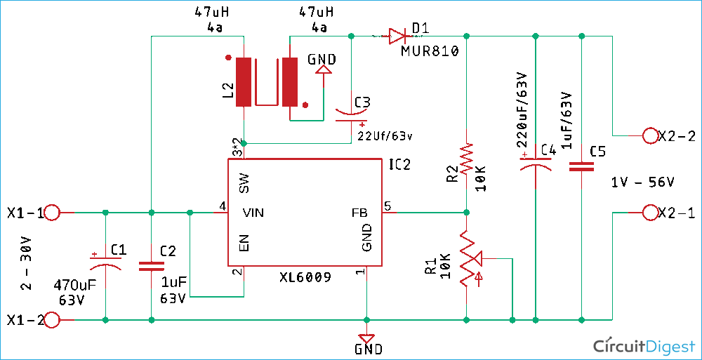
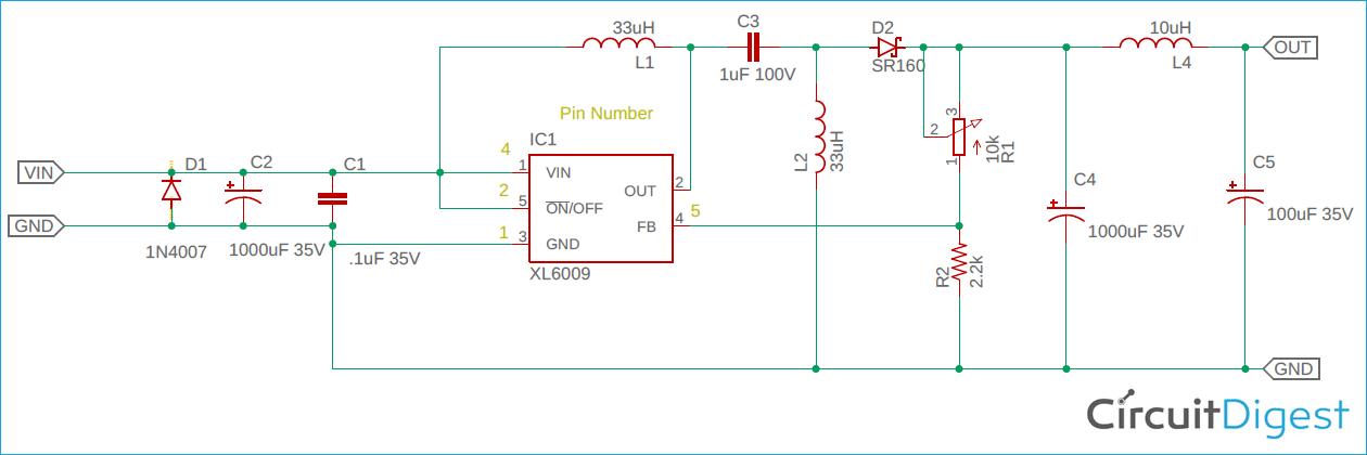
Single Ended Primary Inductor Sepic Converter Design With Xl6009 In this video, we are going to be learning, building, and testing a simplified sepic converter built on top of the popular xl6009 ic.in the field of dc dc co. Pcb for xl6009 based sepic converter. the pcb for our sepic buck boost converter circuit is designed on a single sided board. i have used eagle to design my pcb but you can use any pcb design software of your choice. the 2d image of the top and bottom of the pcb that is generated by eagle is shown below.

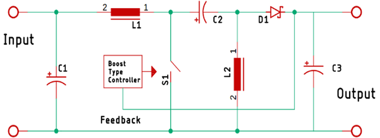
How To Design Xl6009 Based Sepic Buck Boost Converter S Introduction. the single ended primary inductance converter (sepic) is a dc dc converter topology that provides a positive regulated output voltage from an input voltage that varies from above to below the output voltage. this type of con version is handy when the designer uses voltages (e.g., 12 v) from an unregulated input power supply such. 4 switch buck boost architecture. the sepic converter. the sepic converter is the most common and long standing buck boost architecture and is illustrated in fig 1. fig 1. the ltspice circuit can be downloaded here: sepic converter. the architecture is very similar to a boost converter. This section shows how the sepic multiplied boost converter is derived from the sepic and boost topologies. simple boost converter. this is one of the most basic converter topologies. it produces v out > v in. figure 5. simple boost converter. single ended primary inductance converter (sepic) the sepic is a member of the buck boost family. The xl6009 is both a buck and a boost 3a voltage converter that can take an input voltage an boost it to 35v. but can it go further further?input range: 3.8v.

Buck Boost Regulator Circuit Design Using Xl6009 With Adjustable 3 3v This section shows how the sepic multiplied boost converter is derived from the sepic and boost topologies. simple boost converter. this is one of the most basic converter topologies. it produces v out > v in. figure 5. simple boost converter. single ended primary inductance converter (sepic) the sepic is a member of the buck boost family. The xl6009 is both a buck and a boost 3a voltage converter that can take an input voltage an boost it to 35v. but can it go further further?input range: 3.8v. And90136 d. introduction. the single−ended primary−inductor converter (sepic) is a type of dc dc converter that allows the electrical potential (voltage) at its output to be greater than, less than, or equal to that at its input. the sepic converter is controlled by the duty cycle of the main switch q1. The regulator can work both in current mode and dc dc converter mode and can be configured to work as boost, buck, buck boost, flyback, sepic or even as an inverting converter. a sample application circuit to make it work as boost converter is given below. the input voltage to be regulated is provided to pin 4 and pin 1 is connected to ground.

Single Ended Primary Inductor Sepic Converter Design With Xl6009 And90136 d. introduction. the single−ended primary−inductor converter (sepic) is a type of dc dc converter that allows the electrical potential (voltage) at its output to be greater than, less than, or equal to that at its input. the sepic converter is controlled by the duty cycle of the main switch q1. The regulator can work both in current mode and dc dc converter mode and can be configured to work as boost, buck, buck boost, flyback, sepic or even as an inverting converter. a sample application circuit to make it work as boost converter is given below. the input voltage to be regulated is provided to pin 4 and pin 1 is connected to ground.

Xl6009 Buck Boost Converter Easyeda Open Source Hardware Lab

Comments are closed.