How To Drive A 7 Segment Display The Learning Circuit

15 Bcd To 7 Segment Decoder Circuit Diagram Robhosking Diagram Karen walks through how to use one type of decoder in a circuit, a bcd to 7 segment. while this circuit would typically use a microcontroller to provide the. This circuit is helpful for practicing counting in binary as well as learning how to drive a 7 segment display. this circuit uses a common anode 7 segment led display that is driven by an sn74ls47n decoder. if you would like to create a circuit using a common cathode led display, a 74ls48 decoder could be used and the power would need to be.

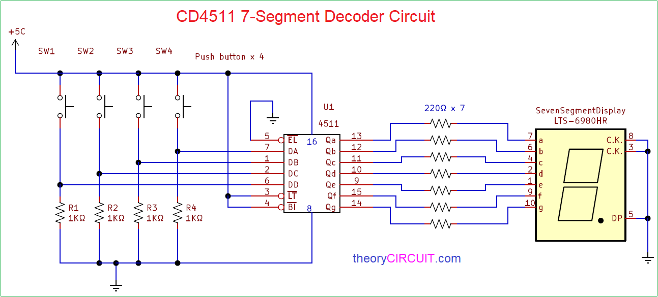
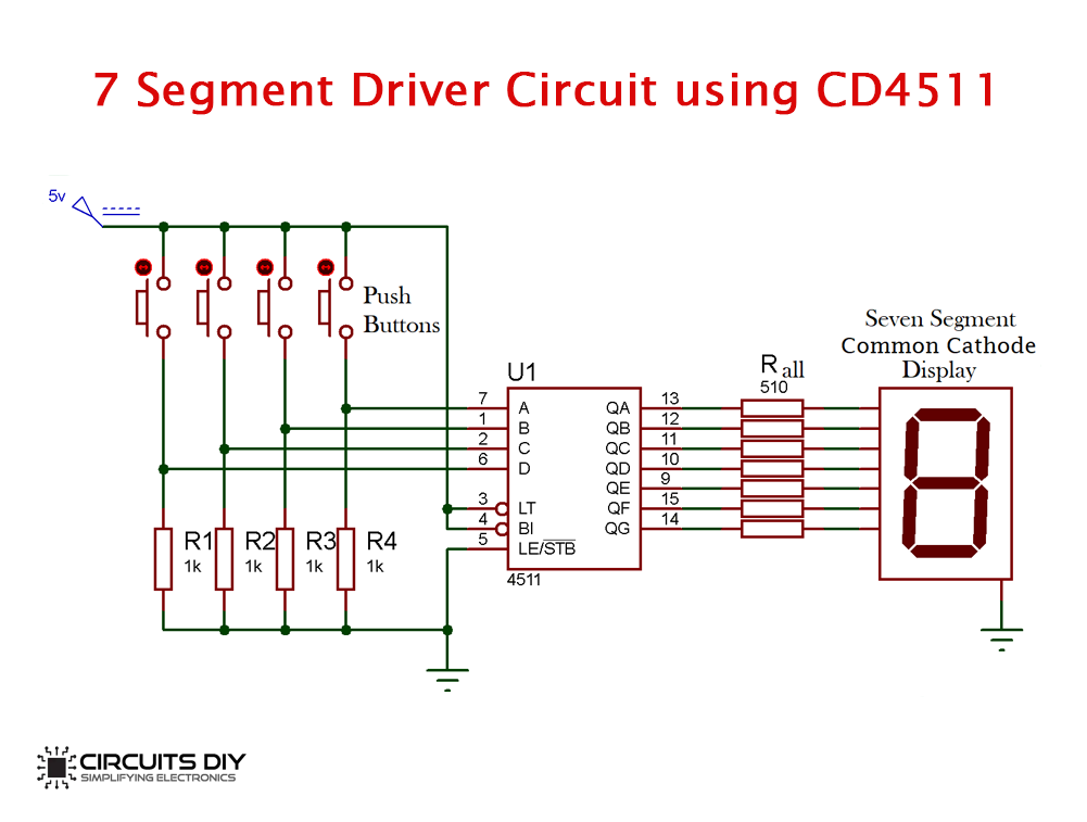
How To Drive A 7 Segment Display Using Bcd Driver Ic Cd4511 Circuit schematic. the schematic for the 7 segment led display connected to the arduino is shown below. the connections are fairly simple. we utilize 8 digital pins of the arduino and the ground terminal. the written form of the above schematic is shown below for the pin connections. 7 segment led display pin. The 7 segment display, also written as “seven segment display”, consists of seven leds (hence its name) arranged in a rectangular fashion as shown. each of the seven leds is called a segment because when illuminated the segment forms part of a numerical digit (both decimal and hex) to be displayed. an additional 8th led is sometimes used. The 7 segment led is really a versatile display device. for this project, we will show how to create all the alphabetical characters which can be shown at a 7 segment led dsiplay. this includes alphabet characters, a, b, c, c, d, e, f, h, h, l, l, o, o, p, s. these are pretty much the only characters of the alphabet which can be produced. A 4 digit 7 segment led display has 12 pins. 8 of the pins are for the 8 leds on each of the 7 segment displays, which includes a g and dp (decimal point). the other 4 pins represent each of the 4 digits from d1 d4. the pinout for the led segment is shown below. the potentiometer that is used can be of any value.

Comments are closed.