How To Make A Pwm Generator With 555 Timer On Proteus

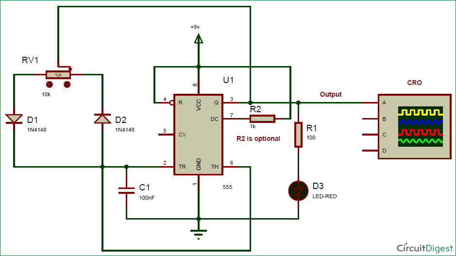
Pwm Generation Using 555 Timer Ic Proteus Simulation Youtube Pwm generator circuit using 555 timer and proteus simulation softwareabout this video: pulse width modulation (pwm) is a fancy term for describing a type of. To implement the pulse width modulation using 555 timer, we are using the simulation in proteus isis. to implement the 555 timer pwm just follow the simple steps given next: fire up your proteus software. fix first five components from the "pick library" at the working area.

555 Timer Pwm Generator Circuit Diagram #pwm #electronics 555 timer ic pwm (pulse width modulation) generator circuit on proteus circuit link: electrobuff 2024 03 555 timer ic p. The video tutorial is about simulating a simple pulse generator using 555 timer circuit simulated in proteus. the output frequency can be varied by adjusting. How to generate pwm signal using 555 timer ic?. The above circuit is a bi stable latch using trigger and threshold inputs of 555 timer. the output of uc (upper comparator) which is reset input to rs latch is high when the threshold input is high or greater than 2 3 vcc, so it is pulled down. when the reset input is high with low set input to the latch, the output is reset i.e., low.
How To Make A Pwm Generator With 555 Timer On Proteus шїыњшїш щ Dideo How to generate pwm signal using 555 timer ic?. The above circuit is a bi stable latch using trigger and threshold inputs of 555 timer. the output of uc (upper comparator) which is reset input to rs latch is high when the threshold input is high or greater than 2 3 vcc, so it is pulled down. when the reset input is high with low set input to the latch, the output is reset i.e., low. Place the 555 timer ic on the breadboard and connect pin 8 to vcc and pin 1 to gnd. use a jumper wire, to connect pin 2 and pin 6 together. connect pin 4 to vcc. use the 0.01uf capacitor to connect pin 2 to gnd. connect an led with a 100 Ω resistor to pin 3. use a 1k resistor to connect pin 7 to vcc. connect the middle pin of the variable. In the circuit above, we see a 555 timer configured as an astable oscillator. the 555 timer will generate the pulse width modulation signal at a specific duty cycle and switch the mosfet transistor q1. the mosfet transistor in this circuit is the irf540 mosfet transistor. d1 is an led that will be made brighter and dimmer by the pwm signal. but.

Comments are closed.