How To Read A Heat Pump Wiring Diagram Schematic Connection

How To Read A Heat Pump Wiring Diagram Schematic Connection Youtube In this hvac training video, i show how to read the wiring diagrams of a heat pump to understand how each of the components work and how they are wired. we c. Schematic & connection! how to read the wiring diagrams of a heat pump to understand how each of the components work and how they are wired. we cover the schematic wiring diagram, the connection diagram, and the legend, as well as explaining how the defrost board works.

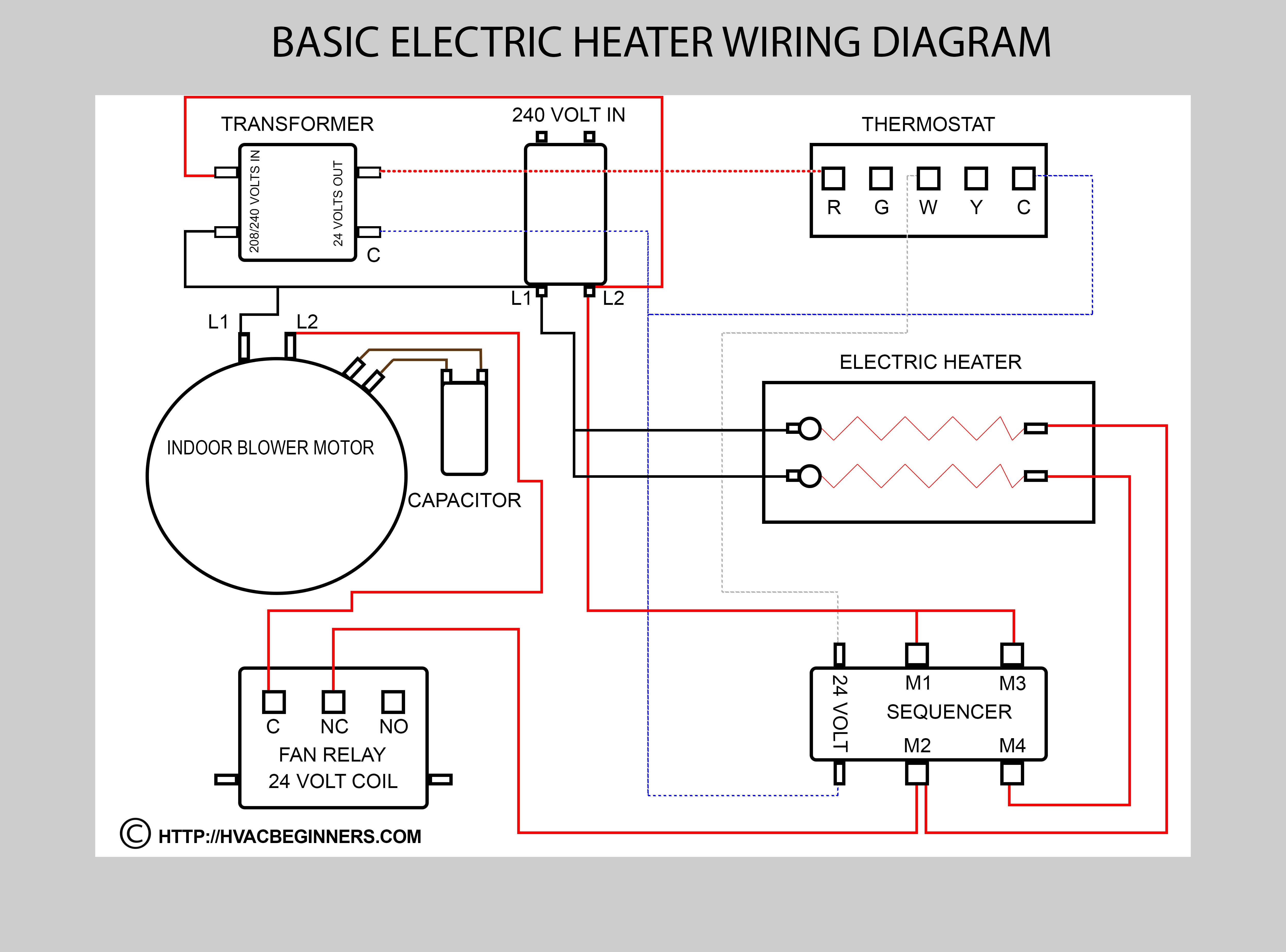
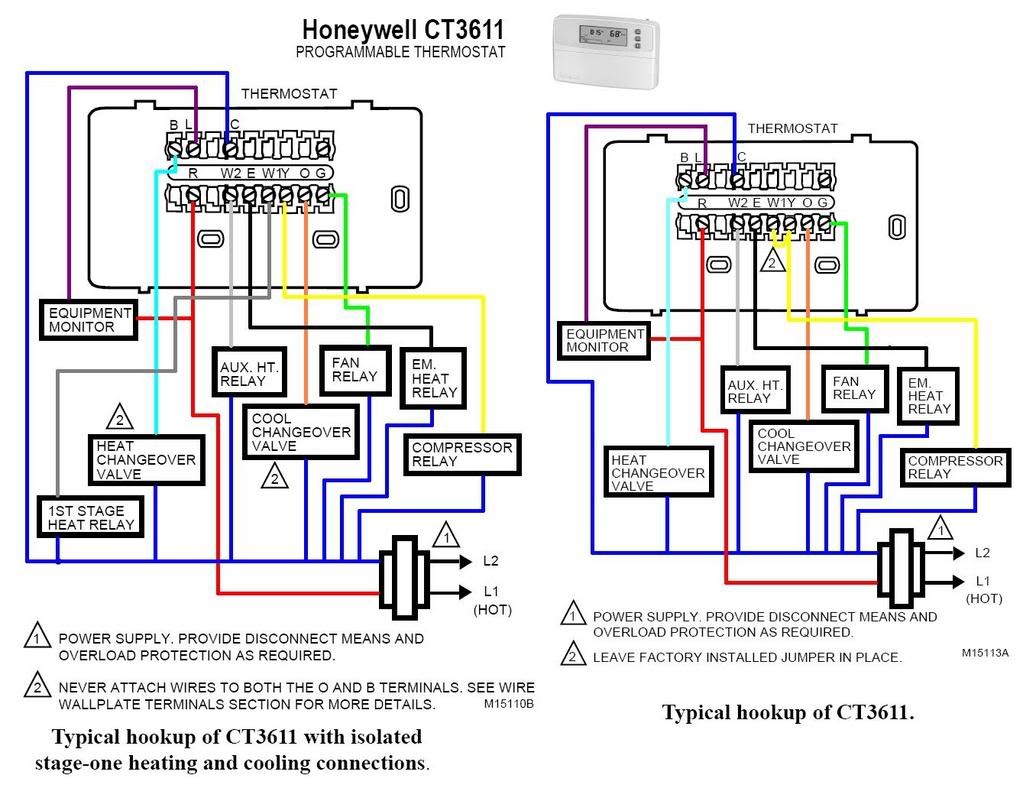
Heat Pump Wiring Diagram Schematic In summary. a heat pump wiring diagram is a visual representation of how the electrical components of a heat pump system are connected. it shows the connections between the thermostat, compressor, fan motor, and other parts, allowing technicians to troubleshoot and repair any issues with the electrical system. It is important to correctly wire these components to ensure proper operation of the heat pump. the wiring diagram provided by the manufacturer should be followed to connect the wires to their respective terminals. 4. indoor unit wiring: the indoor unit of the heat pump includes the air handler and the blower motor. The importance of wiring in a heat pump. the wiring of a heat pump is integral to its operation. the wires serve as the communication channels between the heat pump and its components, carrying signals and electricity that control the system’s functions. proper and efficient wiring is essential for the heat pump to function optimally. The first step to understanding the heat pump schematic diagram is identifying the key components. these typically include the compressor, condenser, evaporator, and expansion valve. these components work together to absorb heat from one location and release it in another, effectively heating or cooling your home. component.

Heat Pump Wiring Diagram Explained The importance of wiring in a heat pump. the wiring of a heat pump is integral to its operation. the wires serve as the communication channels between the heat pump and its components, carrying signals and electricity that control the system’s functions. proper and efficient wiring is essential for the heat pump to function optimally. The first step to understanding the heat pump schematic diagram is identifying the key components. these typically include the compressor, condenser, evaporator, and expansion valve. these components work together to absorb heat from one location and release it in another, effectively heating or cooling your home. component. The heat pump schematic is a diagram that illustrates the various parts and connections of a heat pump system. it serves as a blueprint for understanding how heat pumps operate and how they are configured. by studying the schematic, homeowners, hvac technicians, and engineers can gain a deeper understanding of the inner workings of a heat pump. Heat pump wiring basics (universal principles).
How To Read A Heat Pump Wiring Diagram Schematic The heat pump schematic is a diagram that illustrates the various parts and connections of a heat pump system. it serves as a blueprint for understanding how heat pumps operate and how they are configured. by studying the schematic, homeowners, hvac technicians, and engineers can gain a deeper understanding of the inner workings of a heat pump. Heat pump wiring basics (universal principles).

Heat Pump Schematics And Wiring Diagrams

Comments are closed.