How To Wire 208v And 120v Single Phase And 3 Phase How

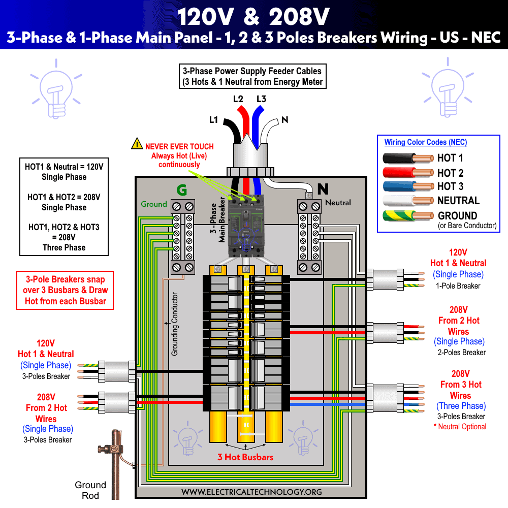
How To Wire 208v And 120v Single Phase And 3 Phase How To Wire 120v The following tutorial shows how to wire 120v single phase breaker box installation in case of 208v three phase panel box for residential application such as lighting or ceiling fan etc. as shown in the fig below, connect a a single pole circuit breaker to any hot busbars i.e. (hot 1, hot 2 or hot 3). the outgoing hot wire from the 1 pole. To configure a 208v ac system, you need phase 1 (black), phase 2 (red), phase 3 (blue), neutral (white), and ground wires. the color scheme may vary depending on your location. but you typically find these wires in 120v, 240v, and 208v ac systems. the wire size and type will depend on the load and the environment.

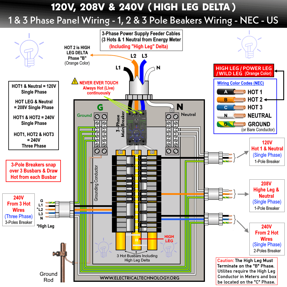
3 Phase Diagram Wiring This video shows how to wire 208v and 120v. single phase and 3 phase. 3 pole breaker for single phase 120v if you only pull out a single hot wire from the br. Voltage between high leg and neutral = 1 2 x 220v x √3 = 208v (1 Φ). voltage between two hot phases = 120v x 2 = 240v (1 Φ). voltage between three phases = 240v (3 Φ). these are the general setup and may vary and depend on the installation e.g. neutral wire may be needed for three phase 240v outlets etc. The 208v 3 phase wiring diagram illustrates the connections and components involved in a three phase electrical system. it shows how the three phases (labeled a, b, and c) are connected to the main electrical panel and distributed to different loads. it also includes information about the neutral wire and ground connections. Testing the 208v wiring in single phase. switch on the electricity at the main panel or at the circuit breaker. make sure the power is back on by checking the led indicators of the switchboard. turn on the appliance. make sure the appliance plug is attached properly.

How To Wire 208v And 120v Single Phase And 3 Phase Youtube The 208v 3 phase wiring diagram illustrates the connections and components involved in a three phase electrical system. it shows how the three phases (labeled a, b, and c) are connected to the main electrical panel and distributed to different loads. it also includes information about the neutral wire and ground connections. Testing the 208v wiring in single phase. switch on the electricity at the main panel or at the circuit breaker. make sure the power is back on by checking the led indicators of the switchboard. turn on the appliance. make sure the appliance plug is attached properly. The wiring diagram for converting a single phase to a three phase system will typically show the electrical connections between the required components, such as the power supply, motor, and control devices. it will also indicate the proper wiring configurations and the appropriate conductor sizes. common components found in a single phase to. Single phase 208v wiring involves one hot wire, one neutral wire, and a ground wire. the hot wire carries the electrical current from the source to the devices being powered, while the neutral wire provides a return path for the current. the ground wire is used for safety purposes and helps to prevent electrical shocks and other hazards.

208v 3 Phase Wiring The wiring diagram for converting a single phase to a three phase system will typically show the electrical connections between the required components, such as the power supply, motor, and control devices. it will also indicate the proper wiring configurations and the appropriate conductor sizes. common components found in a single phase to. Single phase 208v wiring involves one hot wire, one neutral wire, and a ground wire. the hot wire carries the electrical current from the source to the devices being powered, while the neutral wire provides a return path for the current. the ground wire is used for safety purposes and helps to prevent electrical shocks and other hazards.

Comments are closed.