How To Wire A Turn Signal Flasher Three Prong Wiring Diagram Ima

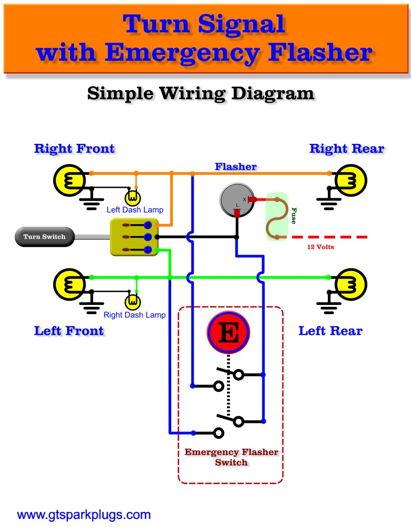
Simple Wiring Diagram Turn Signal Flasher In this video we will be going over the basics on how to wire a flasher relay commonly used in turn signals and hazard light. this is part 4 of the how to re. Step 6: test the flasher relay. once all the wiring is complete, reconnect the power to your vehicle’s electrical system and test the flasher relay. activate the turn signals and ensure that they are flashing at the correct speed and rhythm. by following these steps, you can successfully wire a 3 pin flasher relay for optimal performance.

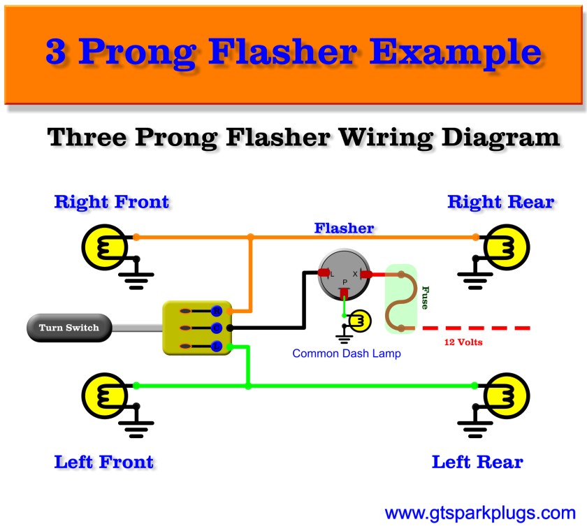
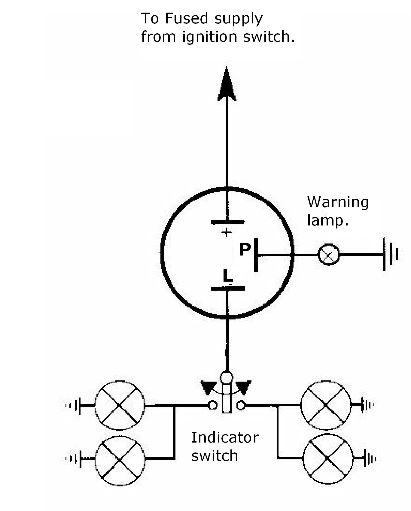
3 Prong Flasher Wiring Diagram Wiring Diagram In this video, i show you how i would wire an automotive flasher relay, (which is also called a turn signal, directional, and blinker circuit) for a car, tru. A wiring diagram can help you safely complete your project, so take the time to find one that matches the make and model of your 3 pin flasher relay. turn signal wiring using relays factory five racing forum. turn signal wiring s 10 forum. 3 pin led turn signal flasher relay mgi sdware. wiring diagrams to assist you with connecting up. This circuit will produce a blinking, pulsing light signal and is perfect for use on any vehicle such as a motorcycle atv side by side ect. the speed of the. The 3 pin flasher relay 12v diagram is designed to provide a simple and reliable way to control the flashing of the turn signals. when the switch is turned on, the flasher relay receives power from the battery via the x pin. the relay then starts to alternate the power between the l pin and the p pin, causing the turn signal bulbs to flash.

How To Wire A Turn Signal Flasher Three Prong My Wiring ођ This circuit will produce a blinking, pulsing light signal and is perfect for use on any vehicle such as a motorcycle atv side by side ect. the speed of the. The 3 pin flasher relay 12v diagram is designed to provide a simple and reliable way to control the flashing of the turn signals. when the switch is turned on, the flasher relay receives power from the battery via the x pin. the relay then starts to alternate the power between the l pin and the p pin, causing the turn signal bulbs to flash. Step 4: identify and connect the power source. next, locate the power source for your turn signal system. this can be the vehicle’s battery or fuse box. connect the positive and negative wires from the turn signal switch to the power source to provide electricity for the system. Step 2: identify the flasher relay and its pins. after gathering the necessary tools and materials for wiring your 12 volt flasher, the next step is to identify the flasher relay and its pins. the flasher relay is a small electronic device that controls the flashing of your vehicle’s turn signals. it is usually located near the fuse panel or.

Comments are closed.