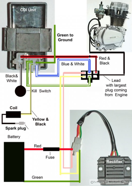
How To Wire Cdi Box

Yamaha Cdi Box Wiring Diagram The 6 pin cdi comes in the form of a black box fitted with a male connector up top. there are six different electrical pins inside of this connector that serve to provide power to the machine by syncing the various parts of the ignition system. these six pins connect the ignition power to the cdi, the ignition coil, the timing trigger or pulse. Capacitor discharge ignition system. cdi is the most common ignition system in motorcycles and motorbikes. in this video i will show you how to wire a cdi in.

How To Wire A Cdi Box #wirings #nonpromechanic #cdisubscribe for more vids! thankyou🙂for sponsorship⤵️⤵️⤵️nonpromechanic28@gmail fb(nonpro mechanic). The 6 wires of a cdi connect the power, pickup trigger, ground, and ignition coil. trace each wire in the wiring diagram during troubleshooting. use a multimeter to test trigger, power, ground, and coil connections. know the spark generation sequence including signal trigger, amplification, energy storage and discharge. Prepare the wires. cut the wires to the appropriate lengths and strip the insulation off the ends. this will make it easier to connect the wires to the cdi box and other electrical components. solder the connections. using a soldering iron, carefully solder the wires to the correct terminals on the cdi box. Installing a high performance 6 pin dc cdi box but the wiring has you stumped? this video has the diagrams to get your engine running right!read more: https:.

How To Wire Cdi Box Prepare the wires. cut the wires to the appropriate lengths and strip the insulation off the ends. this will make it easier to connect the wires to the cdi box and other electrical components. solder the connections. using a soldering iron, carefully solder the wires to the correct terminals on the cdi box. Installing a high performance 6 pin dc cdi box but the wiring has you stumped? this video has the diagrams to get your engine running right!read more: https:. Pin 1: power output – this pin is connected to the ignition coil and provides the high voltage spark. pin 2: ground – this pin is connected to the engine’s ground or chassis. pin 3: charging coil – this pin is connected to the engine’s charging coil, which generates the electrical power for the cdi unit. The green wire brings the pulsing signal from the pickup coil to the cdi box so it knows when to fire the spark plug. the white wire connects the cdi box to the ac voltage output wires from the stator. this provides power to the cdi system. the red wire goes to the positive terminal of the battery and serves as the main power feed for the cdi.

How To Wire Cdi Box Pin 1: power output – this pin is connected to the ignition coil and provides the high voltage spark. pin 2: ground – this pin is connected to the engine’s ground or chassis. pin 3: charging coil – this pin is connected to the engine’s charging coil, which generates the electrical power for the cdi unit. The green wire brings the pulsing signal from the pickup coil to the cdi box so it knows when to fire the spark plug. the white wire connects the cdi box to the ac voltage output wires from the stator. this provides power to the cdi system. the red wire goes to the positive terminal of the battery and serves as the main power feed for the cdi.

Atv Cdi Box Wiring Diagram Four Wire 125cc Wiring Diagram Pictures

Comments are closed.