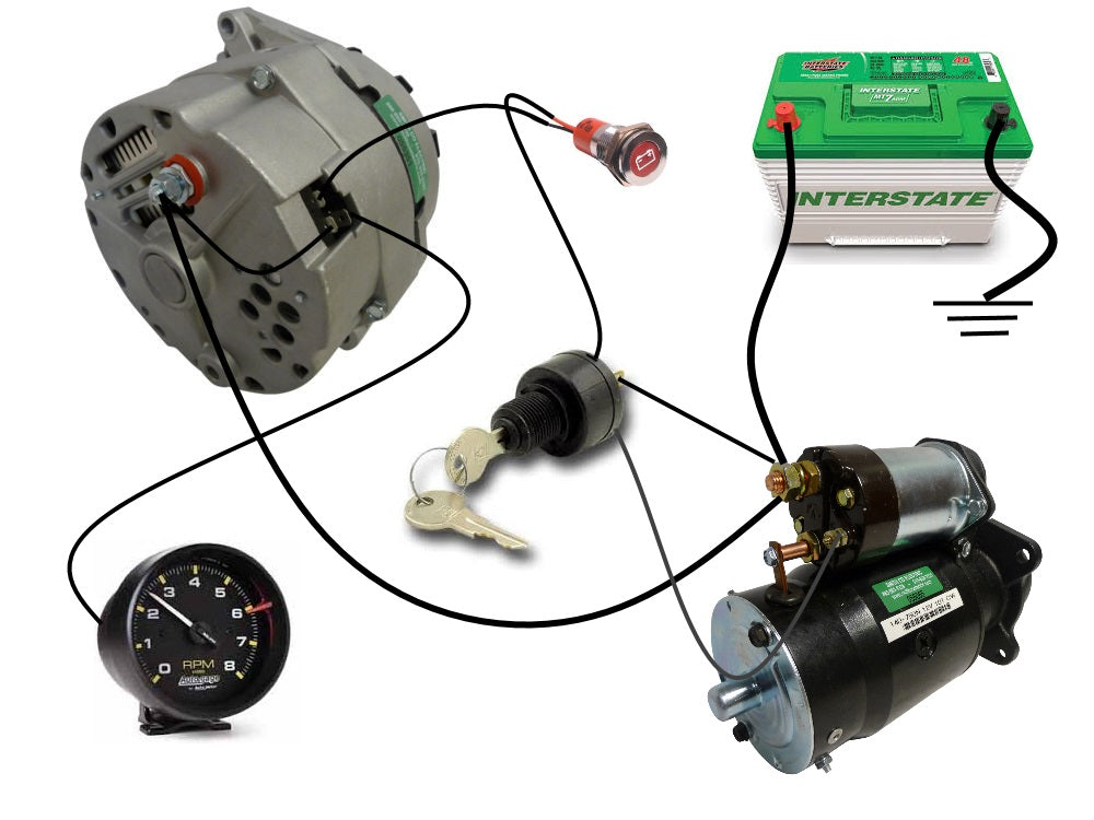
How To Wiring Car Alternator Car Alternator Wiring Diagram 2 Pin Alternator Wiring Diagram

Basic Car Alternator Wiring Diagram In a 2 wire alternator wiring diagram, the output wire is usually connected directly to the battery’s positive terminal, while the voltage sensing wire is connected to the ignition switch or a voltage regulator. this allows the alternator to sense the voltage level in the electrical system and adjust its output accordingly. Here is a step by step guide to wiring a 2 wire alternator: identify the b terminal on the alternator, which is usually marked with a “ ” or “b”. connect a heavy gauge wire from the b terminal to the positive terminal of the vehicle’s battery. identify the l terminal on the alternator, which is usually marked with an “l”.

Alternator Wiring Diagram 2 Wire Step 3: identify the pins and wires on the alternator: examine the 2 pin alternator and identify the pins and wires. typically, one pin is labeled “b” for the battery, and the other pin is labeled “s” or “c” for the stator or sense wire. refer to the wiring diagram for your specific alternator to confirm the pin designations. The connection diagram of an alternator shows how the various components are connected to each other and to the vehicle’s electrical system. the main components of an alternator include the rotor, stator, rectifier, voltage regulator, and the output terminals. the rotor is the rotating part of the alternator that creates a magnetic field. The car alternator connection diagram shows the various connections that are made to the alternator. these connections include the positive and negative terminals, as well as connections to the battery, ignition switch, and various electrical components in the car. the diagram provides a visual representation of how the alternator and its. Now, you can begin wiring your alternator to charge your battery. begin by connecting the alternator’s battery positive wire to the positive terminal on your battery. continue to connect the alternator’s negative terminal to the car’s chassis. then, use cables or wiring harnesses to connect the alternator’s remaining terminals to the.

Mitsubishi 2 Pin Alternator Wiring Diagram The car alternator connection diagram shows the various connections that are made to the alternator. these connections include the positive and negative terminals, as well as connections to the battery, ignition switch, and various electrical components in the car. the diagram provides a visual representation of how the alternator and its. Now, you can begin wiring your alternator to charge your battery. begin by connecting the alternator’s battery positive wire to the positive terminal on your battery. continue to connect the alternator’s negative terminal to the car’s chassis. then, use cables or wiring harnesses to connect the alternator’s remaining terminals to the. This is a three wire alternating wiring diagram showing the connections between the different components of a circuit. the circuit comprises three main wires: battery positive cable, voltage sensing wire, and ignition wire. the ignition input wire is attached to the engine. it conducts electricity from the engine to the alternator while the. The delco remy 2 wire alternator is called “2 wire” because it has two main electrical connections: the positive terminal for power output and the negative or ground connection. this design simplifies the wiring process and makes installation easier. the positive terminal is connected to the battery or power distribution point, while the.

Basic Car Alternator Wiring Diagram This is a three wire alternating wiring diagram showing the connections between the different components of a circuit. the circuit comprises three main wires: battery positive cable, voltage sensing wire, and ignition wire. the ignition input wire is attached to the engine. it conducts electricity from the engine to the alternator while the. The delco remy 2 wire alternator is called “2 wire” because it has two main electrical connections: the positive terminal for power output and the negative or ground connection. this design simplifies the wiring process and makes installation easier. the positive terminal is connected to the battery or power distribution point, while the.

Wiring Diagram 1 Wire Alternator Wiring Digital And Schematic

Comments are closed.