Hvac Wiring Diagrams Schematics

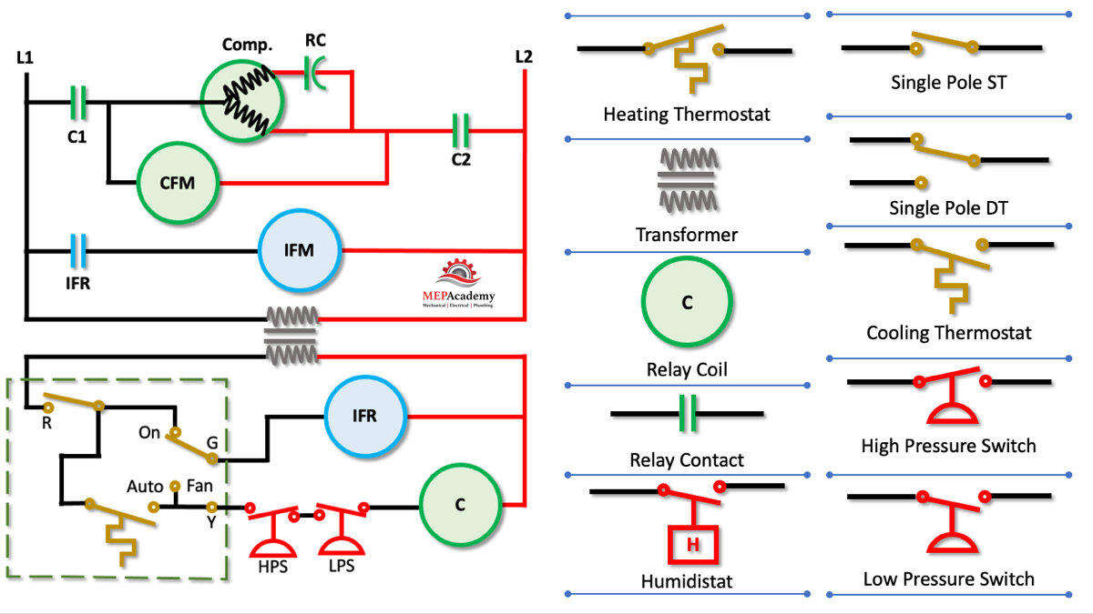
How To Read Wiring Diagrams In Hvac Systems Mep Academy R or rc wire (power) connected to the r power terminal to power the thermostat. w wire (heat), connected to the heating control. g wire (fan) connected to the fan control to operate a blower in your hvac system. y1 wire (cooling) connected to the y terminal compressor refrigerant system. Hvac wiring diagram and legend. we’ll jump right into showing you a schematic diagram for a simple air conditioning unit. we’ll make a ladder diagram using a simple air conditioner as our example. first we have the main electrical supply lines l1 and l2 providing 208 230 volt, single phase power. then we’ll need a transformer to provide.

How To Read Wiring Diagrams In Hvac Systems Mep Academy Loads usually sit at the end of a circuit; after power moves from the power supply through an inline switch or switches, the load or loads are powered up and begin functioning. loads include motors, compressors, contactors, relay coils, and light bulbs. loads perform work and draw amperage. this basic wiring diagram includes all three main. The control wiring diagram includes: power supply connections: the diagram shows how the system is connected to the electrical power source, including the main voltage and ground connections. control devices: it illustrates the various control devices used in the hvac system, such as thermostats, pressure switches, relays, and contactors. August 22, 2018. this video provides an overview of how to read ac schematics. we walk through some of the basics and most common symbols associated with reading air conditioner wiring diagrams. whenever you approach a wiring diagram, look at the whole thing, especially the legend and notes. in many cases, factory wiring will show up as solid. The purpose of hvac wiring diagrams is to provide a visual guide for technicians to follow when installing or servicing the system. by referring to the diagram, technicians can ensure that the electrical connections are made correctly, preventing any hazards or malfunctions. key components depicted in hvac wiring diagrams:.

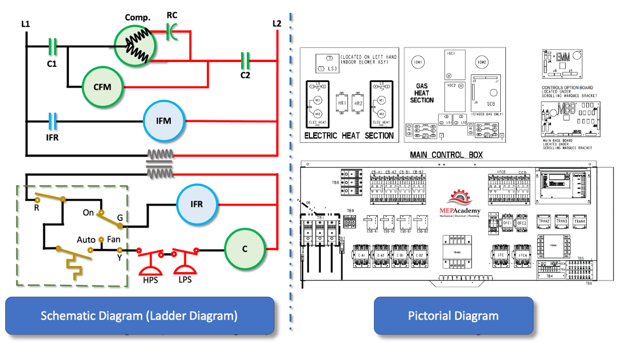
Basic Hvac Wiring Schematics August 22, 2018. this video provides an overview of how to read ac schematics. we walk through some of the basics and most common symbols associated with reading air conditioner wiring diagrams. whenever you approach a wiring diagram, look at the whole thing, especially the legend and notes. in many cases, factory wiring will show up as solid. The purpose of hvac wiring diagrams is to provide a visual guide for technicians to follow when installing or servicing the system. by referring to the diagram, technicians can ensure that the electrical connections are made correctly, preventing any hazards or malfunctions. key components depicted in hvac wiring diagrams:. Understanding symbols and codes: hvac wiring schematics use symbols and codes to represent different components, such as thermostats, motors, relays, and switches. these symbols allow technicians to quickly identify each component and its function within the system. by referring to the schematic, technicians can trace the flow of electricity. Learn how to read hvac electrical wiring diagrams. see the difference between a schematic wiring diagram and a pictorial wiring diagram. see how an electrica.

Comments are closed.