Hydraulic Cylinder Circuit Speed Control And Intensification

Hydraulic Cylinder Hyspecs Hydraulics Australia If the valve spool moves a little bit, the valve flows a little bit. pressure compensation, load sensing or sophisticated electronic control lend the proportional valve superior performance for controlling cylinder speed. no matter the control method, providing your cylinders with a method to control speed is always helpful. About press copyright contact us creators advertise developers terms privacy policy & safety how works test new features nfl sunday ticket press copyright.

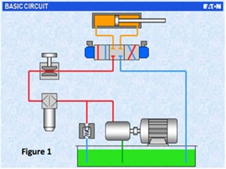
Schematic Diagram Of Hydraulic System Of Hydraulic Cylinder Unit 1 In order to understand how intensification takes place we must first understand one of the basic fundamentals of fluid power: pressure x area = force (force area = pressure) a typical single rod hydraulic cylinder, such as the one illustrated above, extends and retracts by applying hydraulic pressure to either the cap end (extend side) or rod. When a hydraulic system is supplied by a pressure compensating pump, flow controls may be connected in either a meter in or meter out configuration. when metering the flow going into a cylinder (meter in), no pressure intensification will occur. however, this configuration provides less control over the cylinder speed due to overrunning loads. Intensifier circuit using standard cylinders. the schematic diagram in figures 13 6 through 13 9 suggests how to use standard cylinders as an air hydraulic intensifier. this is a quick way to get high ratio intensification for a rush job. a 6 in. bore air cylinder driving a 1.5 in. bore hydraulic cylinder gives an intensification ratio of 16:1. Figure 11 26. meter in flow control circuit with motor type flow divider to minimize heat generation. (shown with cylinder extending at slow speed). figure 11 26 shows a 3 speed flow control circuit using a rotary flow divider. here the cylinder is extending slow speed. with the circuit set up as shown, it defaults to slow speed.

Hydraulic Circuits Speed Control Of Cylinder Meter In Meter Out Circuitођ Intensifier circuit using standard cylinders. the schematic diagram in figures 13 6 through 13 9 suggests how to use standard cylinders as an air hydraulic intensifier. this is a quick way to get high ratio intensification for a rush job. a 6 in. bore air cylinder driving a 1.5 in. bore hydraulic cylinder gives an intensification ratio of 16:1. Figure 11 26. meter in flow control circuit with motor type flow divider to minimize heat generation. (shown with cylinder extending at slow speed). figure 11 26 shows a 3 speed flow control circuit using a rotary flow divider. here the cylinder is extending slow speed. with the circuit set up as shown, it defaults to slow speed. Discuss the source of differences in travel length and speed for series hydraulic circuits. given two cylinders with the following dimensions in a series relationship, calculate the extension distance of the downstream cylinder given the upstream cylinder fully extends. cap = 1 3 4” rod = 5 8. travel = 6”. Connection and operation of simple, practical hydraulic circuits. design and operation of a directional valve, lever operated . ex. 3 1 cylinder control control of the direction, force, and speed of a cylinder. design and operation of a directional valve, lever operated . effect of a change in system pressure and flow rate on the force and.

Comments are closed.