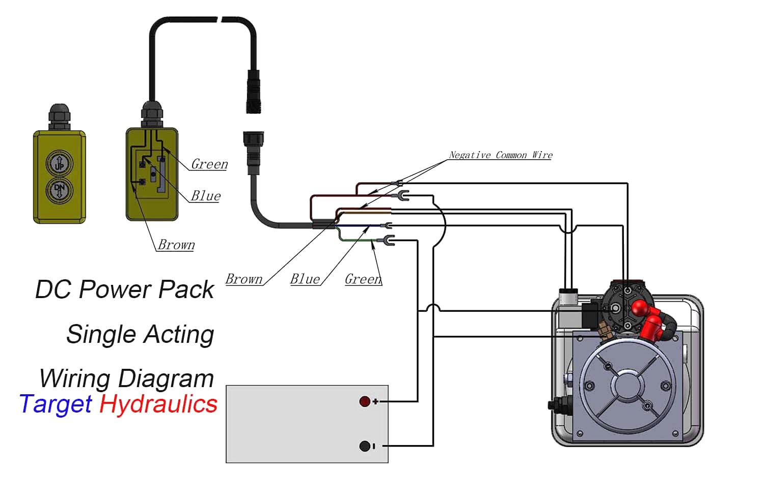
Hydraulic Dump Trailer Pump Wiring Diagram

Dump Bed Electric Motor Wiring Diagrams In a typical wiring diagram for a hydraulic dump trailer, the battery is connected to the hydraulic pump via a switch and solenoid. when the switch is engaged, power flows from the battery to the solenoid, which then activates the pump. this causes the hydraulic system to operate and lift or lower the trailer bed as needed. Understanding wiring diagrams. a dump trailer hydraulic pump wiring diagram is your roadmap to troubleshooting and repair. these diagrams show how power is distributed throughout the trailer’s hydraulic system, highlighting connections between the battery, pump, solenoids, and control switches.
Dump Trailer Double Acting Pump Wiring Diagram This wiring diagram provides a visual representation of how all the electrical components of the hydraulic pump system are connected. typically, a dump trailer hydraulic pump wiring diagram will include components such as the battery, solenoid, motor, pump, and switch. the battery supplies power to the solenoid, which then activates the motor. Hydraulic dump trailers use a series of pumps, valves, and hoses to move fluid from the trailer’s reservoir to its various components. the wiring diagram will show where all of the components are located and how they are connected. it will also provide information about the type of connections each component needs and the type of fluid used. Wiring diagrams. for those unfamiliar with the process of wiring a hydraulic dump trailer, the first step is to obtain a wiring diagram. these diagrams provide a comprehensive overview of the entire wiring system and can help identify any potential problems or electrical issues. it is important to use the correct diagram, as some diagrams may. You will run power in from the 12 volt source to the switch. there is likely a single input from the 12 volt power source. then one output for up and one for down that will attach to the hydraulic pumps wiring accordingly. there is also likely a terminal for a ground. if you can tell me the make and model of the hydraulic pump i may be able to.

Big Tex Dump Trailer Hydraulic Pump Wiring Diagram Pdf Wiring Wiring diagrams. for those unfamiliar with the process of wiring a hydraulic dump trailer, the first step is to obtain a wiring diagram. these diagrams provide a comprehensive overview of the entire wiring system and can help identify any potential problems or electrical issues. it is important to use the correct diagram, as some diagrams may. You will run power in from the 12 volt source to the switch. there is likely a single input from the 12 volt power source. then one output for up and one for down that will attach to the hydraulic pumps wiring accordingly. there is also likely a terminal for a ground. if you can tell me the make and model of the hydraulic pump i may be able to. Mount the power unit using two, 3 8 16 x 3 4 mounting bolts (diagram a 3). connect hydraulic lines to ports “a” top & “b” bottom (diagram a 4).a. connect the “a” port hose to the base of the cylinder.b. connect the “b” port hose to the rod end of the cylinder. remove the filler breather cap and fill the reservoir with hydraulic. The dump trailer solenoid wiring diagram shows the connections between the various components of the dump trailer’s electrical system. typically, the solenoid is connected to the battery, power source, switches, and hydraulic pump. the diagram provides a visual representation of how these components are interconnected, allowing you to trace.
Bri Mar Dump Trailer Wiring Diagram For Your Needs Mount the power unit using two, 3 8 16 x 3 4 mounting bolts (diagram a 3). connect hydraulic lines to ports “a” top & “b” bottom (diagram a 4).a. connect the “a” port hose to the base of the cylinder.b. connect the “b” port hose to the rod end of the cylinder. remove the filler breather cap and fill the reservoir with hydraulic. The dump trailer solenoid wiring diagram shows the connections between the various components of the dump trailer’s electrical system. typically, the solenoid is connected to the battery, power source, switches, and hydraulic pump. the diagram provides a visual representation of how these components are interconnected, allowing you to trace.

Dump Trailer Hydraulic Pump Troubleshooting Solution 2023

Comments are closed.