Hydraulic Pump Solenoid Wiring

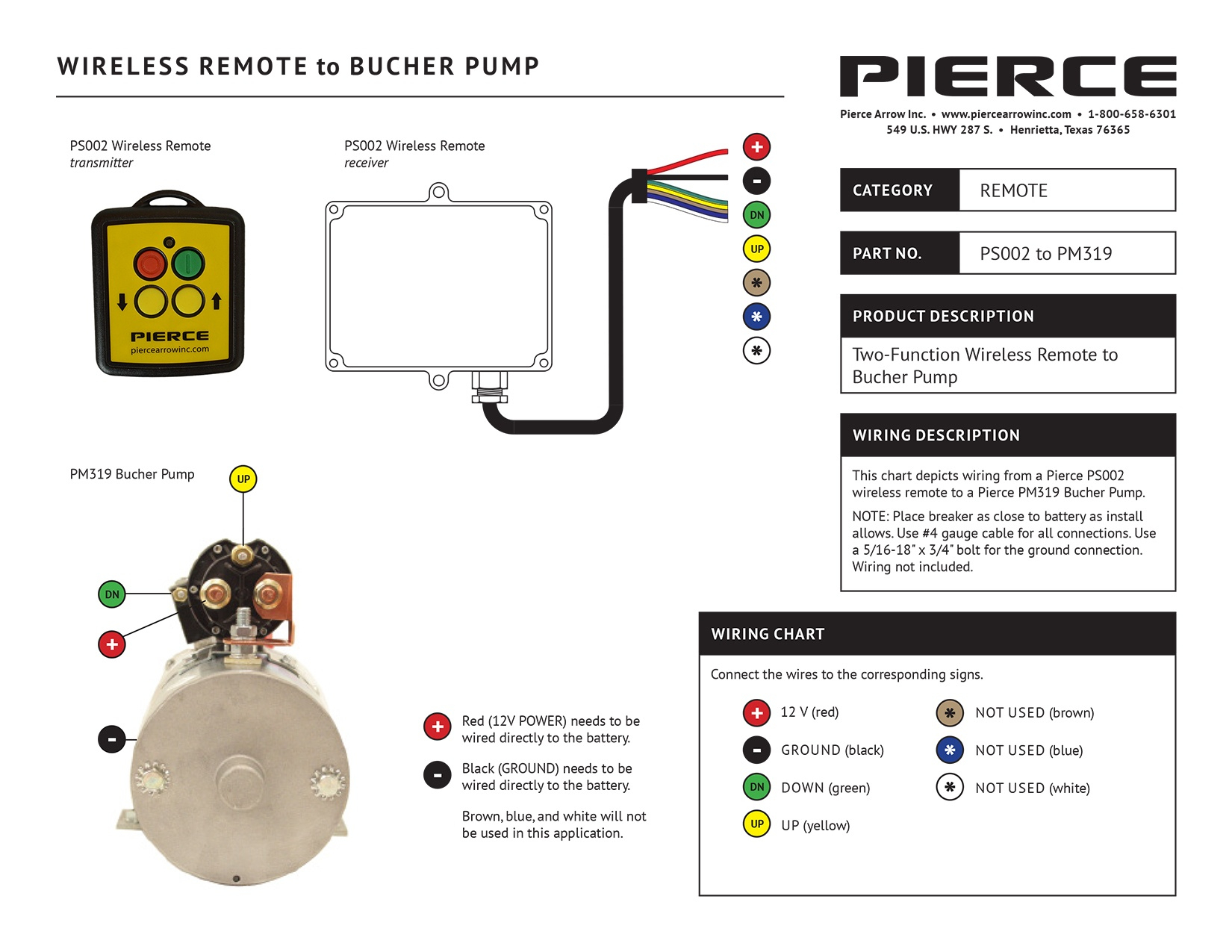
Solenoid Hydraulic Pump Motor Wiring Diagram Manual E Books 12 Volt To understand how a hydraulic solenoid works, it is helpful to examine its wiring diagram. this diagram provides a visual representation of the electrical connections and components involved in the solenoid’s operation. the wiring diagram typically includes information on the power supply, control circuit, and solenoid coil. Proper wiring ensures that the solenoid receives the necessary electrical signals to operate correctly. here is a step by step guide to help you wire a hydraulic pump solenoid: identify the solenoid terminals: start by locating the solenoid terminals on the housing. modern solenoids usually have two terminals, a positive ( ) and a negative ( ).

Hydraulic Pump Solenoid Wiring Wiring up or connecting a 12 volt dc electric hydraulic pump or power pack is not too complicated if you have the right instructions, tools, cables, and conn. Hydraulic solenoid valves are essential components in any hydraulic power system. they allow the flow of fluid to be controlled with an electrical current, and can be used in a variety of applications, such as controlling the direction of flow, and allowing for the precise timing of operations. in order to ensure that your solenoid valve is. Step by step guide to wiring a 12 volt hydraulic pump. wiring a 12 volt hydraulic pump may seem daunting, but with the right tools and instructions, it can be a relatively simple task. follow the step by step guide below to ensure a successful wiring process and proper functioning of your hydraulic pump. required tools and materials:. Connect the hydraulic line from the base of the cylinder to port “p”. check the torque specification of the hose fittings 6. connect the battery ground cable to the ground terminal of the dc motor (diagram a 3). 7. connect the positive cable from the battery to the start solenoid (diagram a 4).

How To Wire Hydraulic Power Pack Power Unit Diagram Design Step by step guide to wiring a 12 volt hydraulic pump. wiring a 12 volt hydraulic pump may seem daunting, but with the right tools and instructions, it can be a relatively simple task. follow the step by step guide below to ensure a successful wiring process and proper functioning of your hydraulic pump. required tools and materials:. Connect the hydraulic line from the base of the cylinder to port “p”. check the torque specification of the hose fittings 6. connect the battery ground cable to the ground terminal of the dc motor (diagram a 3). 7. connect the positive cable from the battery to the start solenoid (diagram a 4). Mount the power unit using two, 3 8 16 x 3 4 mounting bolts (diagram a 3). connect hydraulic lines to ports “a” top & “b” bottom (diagram a 4).a. connect the “a” port hose to the base of the cylinder.b. connect the “b” port hose to the rod end of the cylinder. remove the filler breather cap and fill the reservoir with hydraulic. Connect the positive cable from the battery to the start solenoid (diagram a 5). (please see battery cable gauge table for proper gauge for your length of cables.) use a wrench to hold the bottom nut in place, to torque the upper nut (to 3 ft. lbs.) to fasten the battery connections. reconnect the two button remote pendant at the quick disconnect.

Comments are closed.