Iron Carbon Phase Diagram 2 вђ Ispatguru

Iron Carbon Phase Diagram 4 Fig 1 iron carbon phase diagram. c is an interstitial impurity in fe. it forms a solid solution with alpha, gamma and delta phases of iron. maximum solubility of c in alpha iron is 0.025 % at 727 deg c. body centred cubic (bcc) iron has relatively small interstitial positions. maximum solubility of c in the face centred cubic (fcc) gamma iron. Iron carbon phase diagram 2. home; properties of carbon steels; iron carbon phase diagram 2; iron carbon phase diagram 2. satyendra; july 18, 2023; about ispatguru.

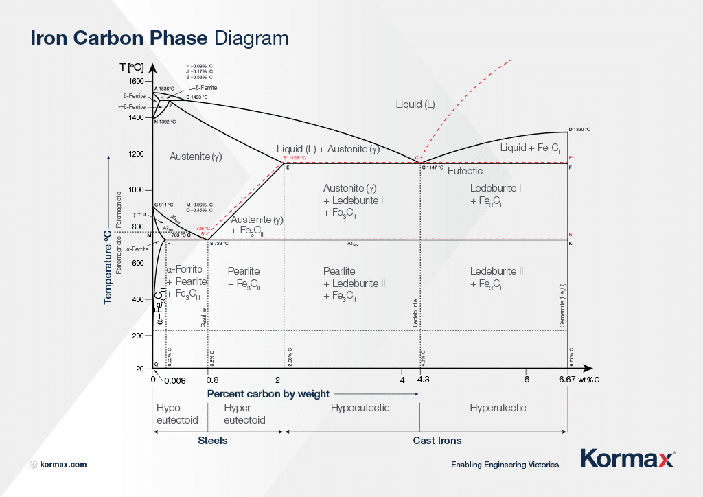
What Is The Iron Carbon Phase Diagram Pdf вђ Learn Mechanical The fe c phase diagram provides temperature composition map of where the two phases (austenite and ferrite) occur. it also indicates where mixtures of these two phases can be expected. the fe c phase diagram is shown in fig 2. in pure iron, austenite transforms to ferrite on cooling to 912 deg c. The weight percentage scale on the x axis of the iron carbon phase diagram goes from 0% up to 6.67% carbon. up to a maximum carbon content of 0.008% weight of carbon, the metal is simply called iron or pure iron. it exists in the α ferrite form at room temperature. from 0.008% up to 2.14% carbon content, the iron carbon alloy is called steel. The iron carbon phase diagram is an equilibrium diagram that explains the phases or microstructure of iron carbon alloys (carbon steels and cast irons) at different temperatures and carbon percentages. on the x axis, we have the carbon concentrations from 0% to 6.67%. on the y axis, we have the temperature of the phase, ranging from 0°c (32°f. The iron carbon phase diagram is a graphical representation of the different phase states that iron and its alloy can experience. it is a great tool for understanding the microstructure of iron and iron alloys and how they should behave. this article will help you understand what the diagram is, how it works, and the information it contains on.

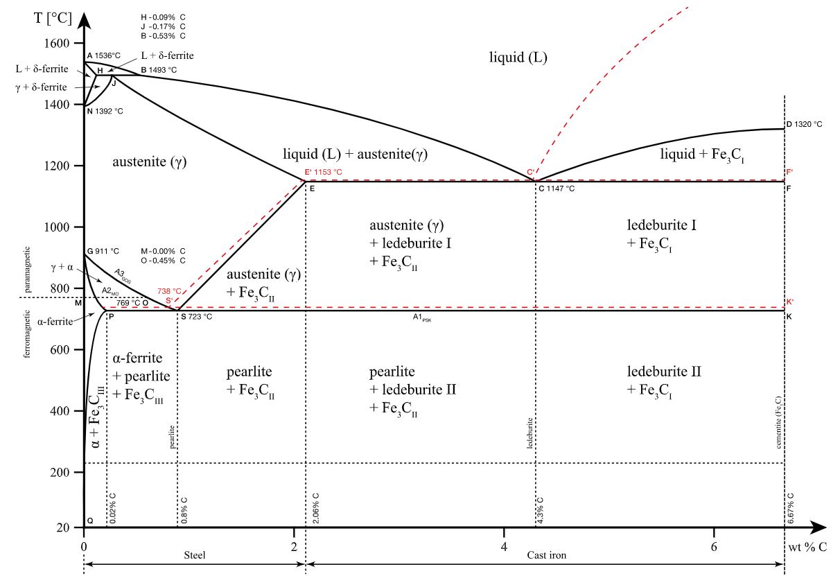
The Iron Carbon Phase Diagram Kormax The iron carbon phase diagram is an equilibrium diagram that explains the phases or microstructure of iron carbon alloys (carbon steels and cast irons) at different temperatures and carbon percentages. on the x axis, we have the carbon concentrations from 0% to 6.67%. on the y axis, we have the temperature of the phase, ranging from 0°c (32°f. The iron carbon phase diagram is a graphical representation of the different phase states that iron and its alloy can experience. it is a great tool for understanding the microstructure of iron and iron alloys and how they should behave. this article will help you understand what the diagram is, how it works, and the information it contains on. Iron carbon phase diagram with detailed explanation: if the percentage of the carbon is in the range of 0 to 2.11 % then it is called steel and if the percentage of carbon is in the range of 2.11 to 6.67% then it is called cast iron. as the carbon content increases, it produces more iron carbide volume and that phase will exhibit high hardness. The iron–carbon equilibrium diagram that started to be used in the 1960s is shown in fig. 1. the concentration and temperature at the important points and their meanings are given in table 1. typical structures with various contents of carbon are shown in fig. 2. pure iron has two allotropes.

Iron Carbon Phase Diagram Diagram Teaching Line Chart Iron carbon phase diagram with detailed explanation: if the percentage of the carbon is in the range of 0 to 2.11 % then it is called steel and if the percentage of carbon is in the range of 2.11 to 6.67% then it is called cast iron. as the carbon content increases, it produces more iron carbide volume and that phase will exhibit high hardness. The iron–carbon equilibrium diagram that started to be used in the 1960s is shown in fig. 1. the concentration and temperature at the important points and their meanings are given in table 1. typical structures with various contents of carbon are shown in fig. 2. pure iron has two allotropes.

Diagram N2 Phase Diagram Mydiagram Online

Comments are closed.