Isometric View Drawing Step By Step Engineering Drawing Orthographic

Orthographic Projection From Isometric View In Engineering Drawing Learn how to draw isometric views with simple and clear steps in this engineering drawing tutorial. watch the video and improve your skills. In this video, i have explained how to draw an orthographic view of an object from an isometric view. it explains how a three dimensional object can be repre.

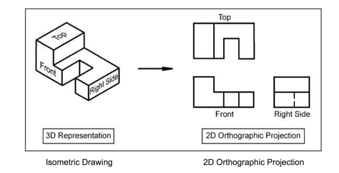
Orthographic To Isometric Drawing Exercises "learn how to draw an orthographic projection using isometric view in this step by step tutorial. using a real life example and 3d animation, this video will. Table of contents drawing isometric from orthographic view 1. understanding the ebook drawing isometric from orthographic view the rise of digital reading drawing isometric from orthographic view advantages of ebooks over traditional books 2. identifying drawing isometric from orthographic view exploring different genres considering fiction vs. Isometric drawing. the representation of the object in figure 2 is called an isometric drawing. this is one of a family of three dimensional views called pictorial drawings. in an isometric drawing, the object’s vertical lines are drawn vertically, and the horizontal lines in the width and depth planes are shown at 30 degrees to the horizontal. Only one view of the object is drawn. this is different from an orthographic projection, in which three views of the object are drawn each showing the front, the top and the side surfaces separately. in engineering, always, the orthographic drawings are preferred and used. the reason is that the isometric drawings have limitations as follows 1.

How To Draw Isometric View Middlecrowd3 Isometric drawing. the representation of the object in figure 2 is called an isometric drawing. this is one of a family of three dimensional views called pictorial drawings. in an isometric drawing, the object’s vertical lines are drawn vertically, and the horizontal lines in the width and depth planes are shown at 30 degrees to the horizontal. Only one view of the object is drawn. this is different from an orthographic projection, in which three views of the object are drawn each showing the front, the top and the side surfaces separately. in engineering, always, the orthographic drawings are preferred and used. the reason is that the isometric drawings have limitations as follows 1. Using the reductive method, convert the following orthographic drawing to an isometric drawing. step 1: determine the total length, width and height of the imaginary bounding box which surrounds the object. step 2: draw a cube which would encompass the object based on the measured length, width and height. The term "isometric" comes from the greek word for "equal measure". it implies that in a projection, the scale along each axis of the projection is the same. in isometric views, all lines on each axis are parallel to each other, and the lines do not converge. in computer graphics it gives a 3d model representation without the distortion caused.

Orthographic Projection Principles Conversions Difference Between Using the reductive method, convert the following orthographic drawing to an isometric drawing. step 1: determine the total length, width and height of the imaginary bounding box which surrounds the object. step 2: draw a cube which would encompass the object based on the measured length, width and height. The term "isometric" comes from the greek word for "equal measure". it implies that in a projection, the scale along each axis of the projection is the same. in isometric views, all lines on each axis are parallel to each other, and the lines do not converge. in computer graphics it gives a 3d model representation without the distortion caused.

Comments are closed.