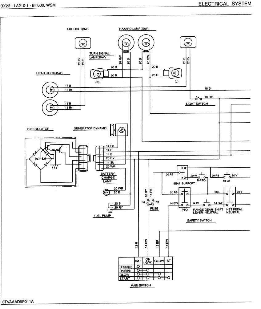
Kubota Rtv900 Wiring Diagram в Wiring Draw And Schematic

Kubota Rtv 900 Wiring Schematic Wiring Diagram Horn switch turn signal lamp rh. (20 w) turn signal lamp lh. (20 w) blinker 1. rotation sensor (if equipped) relay hazard switch. blinker switch. coolant temperature switch head light (37.5 w) light switch output (buzzer) brake lamp switch blinker 2 speed meter (if equipped) blinker 1 fan motor 12v dc output. These diagrams provide the information necessary to make sure that the right parts are connected and operating correctly. that way, you can be sure that your kubota is running at its best. finding the right wiring diagram for your kubota rtv900 can be tricky. there are a lot of different models and years out there, and depending on what you.

Kubota Rtv 900 Wiring Diagram Pdf Kubota rtv900 wiring diagrams may vary depending on the model year. for instance, a wiring diagram for a 2004 model will be completely different from one for a 2020 model. it is important to note, however, that all wiring diagrams follow the same general format. each contains three primary sections—the component layout, the power system and. Page 450 rtv900 ts, wsm electrical system (3) gauges traveling speed (rotation) sensor 1) lead terminal voltage 1. disconnect the lead from the speedometer after turning the main switch off. 2. turn the main switch on and measure the voltage with a voltmeter across the lead terminal (red green) and the chassis. This is where kubota rtv 900 wiring diagram pdfs come in. these wiring diagrams are essential for anyone who wants to properly diagnose, repair, or upgrade their kubota rtv 900. the diagrams provide diagrams of every component and connection in the vehicle. this makes it easy to identify problems and determine the steps needed to fix them. Page 26 rtv900, wsm new transmission muffler cover, muffler, hydraulic oil tank, hydraulic cylinder and hydraulic control valve 1. remove the muffler cover (1) and muffler (2). 2. disconnect the quick couplers from hydraulic control valve. 3. remove the cotter pin and clevis pin, then remove the hydraulic cylinder (3).

Kubota Rtv 900 Wiring Schematic Wiring Diagram This is where kubota rtv 900 wiring diagram pdfs come in. these wiring diagrams are essential for anyone who wants to properly diagnose, repair, or upgrade their kubota rtv 900. the diagrams provide diagrams of every component and connection in the vehicle. this makes it easy to identify problems and determine the steps needed to fix them. Page 26 rtv900, wsm new transmission muffler cover, muffler, hydraulic oil tank, hydraulic cylinder and hydraulic control valve 1. remove the muffler cover (1) and muffler (2). 2. disconnect the quick couplers from hydraulic control valve. 3. remove the cotter pin and clevis pin, then remove the hydraulic cylinder (3). Spudhauler, just so you know, i used your wiring diagram that you posted here to find the wiring problem on my radiator fan of my 2007 rtv 900. i later bought a manual online for $10 that has rtv 900 wiring diagrams in it, but your post here was useful for my only real wiring issue. there are so many good folks on this forum, i am just in awe!. There are multiple types of wiring diagrams for the kubota rtv 900. each type has a different purpose and plays a crucial role in the overall process of connecting and operating the entire electrical system of the vehicle. the two main categories for wiring diagrams are: system wiring diagrams. component wiring diagrams.

Comments are closed.