Ladder Diagrams

What Is Ladder Diagram Edrawmax Online Learn how to draw and interpret ladder diagrams, a type of schematic for industrial control logic systems. find out the rules and conventions for wire numbers, rails, rungs, and load devices in ladder diagrams. Learn how to program a plc using ladder logic, a graphical language that resembles relay circuits. find out the seven basic parts of a ladder diagram, the binary and logic concepts, and the fundamental logic functions.

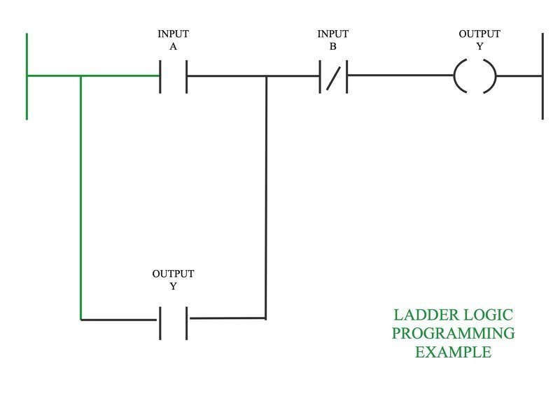
Basics Of Ladder Diagram Plc ladder logic programming tutorial (basics). Learn the basics of ladder logic, a popular plc programming language that mimics electrical circuits. see examples of ladder diagrams, circuit branches, and how to troubleshoot common problems. Ladder logic. ladder logic was originally a written method to document the design and construction of relay racks as used in manufacturing and process control. [1] each device in the relay rack would be represented by a symbol on the ladder diagram with connections between those devices shown. in addition, other items external to the relay rack. Here are some commonly used plc ladder diagram symbols: coil: represented by a circle, it indicates an output device such as a motor or a solenoid valve. when activated, the coil will energize the corresponding output. contact: represented by a line, it indicates an input device such as a push button or a sensor.

Ladder Diagram Schematic Diagram Wiring Diagram Electrical Academia Ladder logic. ladder logic was originally a written method to document the design and construction of relay racks as used in manufacturing and process control. [1] each device in the relay rack would be represented by a symbol on the ladder diagram with connections between those devices shown. in addition, other items external to the relay rack. Here are some commonly used plc ladder diagram symbols: coil: represented by a circle, it indicates an output device such as a motor or a solenoid valve. when activated, the coil will energize the corresponding output. contact: represented by a line, it indicates an input device such as a push button or a sensor. Ladder logic was designed to have the same look and feel as electrical ladder diagrams, but with ladder logic, the physical contacts and coils are replaced with memory bits. let’s take a look. for this program, the relay logic’s ladder diagram is duplicated with ladder logic; no more hard wired logic, but memory locations instead. A plc ladder diagram, also known as a ladder logic diagram or ladder diagram, is a graphical programming language used in programmable logic controllers (plcs) to create electrical circuits or control systems. it is based on the concept of relay logic, where electrical contacts and coils are represented as ladder rungs.

Ladder Diagrams Automation Community Ladder logic was designed to have the same look and feel as electrical ladder diagrams, but with ladder logic, the physical contacts and coils are replaced with memory bits. let’s take a look. for this program, the relay logic’s ladder diagram is duplicated with ladder logic; no more hard wired logic, but memory locations instead. A plc ladder diagram, also known as a ladder logic diagram or ladder diagram, is a graphical programming language used in programmable logic controllers (plcs) to create electrical circuits or control systems. it is based on the concept of relay logic, where electrical contacts and coils are represented as ladder rungs.

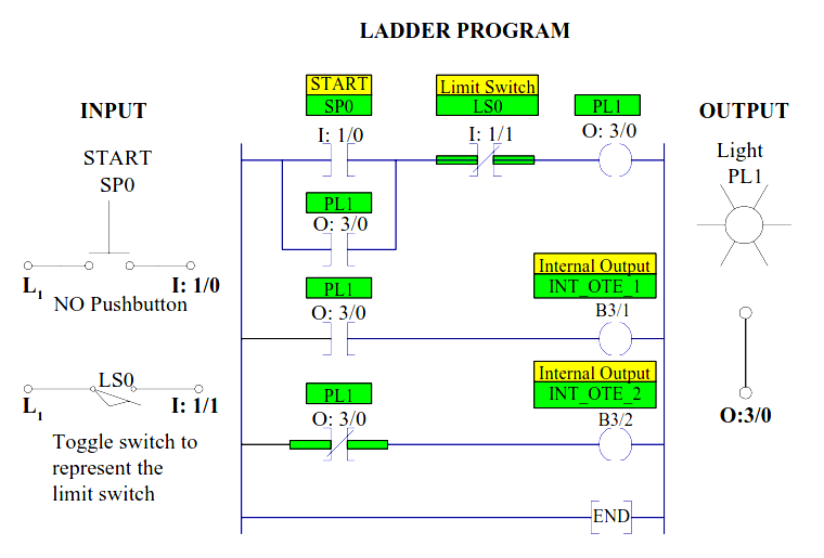
An Example Of Ladder Diagram Download Scientific Diagram

Comments are closed.