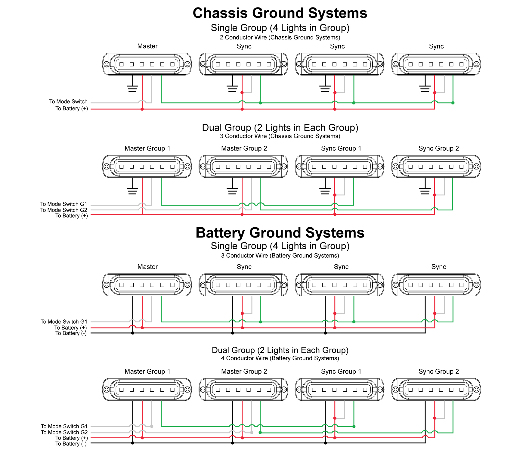
Led Strobe Light Wiring Diagram

How To Install Led Strobe Lights Decoratingspecial In a basic strobe light wiring diagram, the power source is usually a direct current (dc) power supply. the positive ( ) and negative ( ) terminals of the power supply are connected to the corresponding terminals of the strobe light. the capacitor is connected in parallel to the strobe light’s terminals to store and release electrical energy. James with the super bright leds test lab shows you how to wire an led emergency strobe light to a momentary switch. **for permanent installations, be sure.

12v Led Strobe Light Circuit Diagram | timelapse | how to install strobe lights | install & sync | brookings sta 3 | istalling strobe lights on a towtruck |in this video i wire the lights in gr. The wiring diagram for a 4 wire led strobe light is a crucial piece of information for anyone looking to install these lights. this diagram provides a visual representation of the electrical connections, helping to ensure that the installation is done correctly and safely. Begin by placing the components on the breadboard or pcb according to the diagram. pay attention to the polarity of the leds and make sure all connections are secure. use the soldering iron to solder the components together, ensuring strong and reliable joints. step 4: test and fine tune. Groups allow lights to alternate flashes between the groups.to select group, power light and sync light simultaneously (this should flash once to show it is in group one) then remove sync light while maintaining power to red wire. to set to group 2, reapply power to the sync light. it should now flash twice to show that it is in group 2.

Led Strobe Light Wiring Diagram Begin by placing the components on the breadboard or pcb according to the diagram. pay attention to the polarity of the leds and make sure all connections are secure. use the soldering iron to solder the components together, ensuring strong and reliable joints. step 4: test and fine tune. Groups allow lights to alternate flashes between the groups.to select group, power light and sync light simultaneously (this should flash once to show it is in group one) then remove sync light while maintaining power to red wire. to set to group 2, reapply power to the sync light. it should now flash twice to show that it is in group 2. The wiring diagram for a 3 wire led strobe light is relatively simple. it consists of three wires: a positive wire, a negative wire, and a trigger wire. the positive wire is typically red and is connected to the positive terminal of the power source. Grote’s 7679x auxiliary led strobe lights – wiring and flash patterns: red: to vdc (fuse@ 3a) black: to chassis ground. white: for steady burn, apply vdc. yellow: for synchronization – connect yellow wires of all heads together for synchronization (all heads must be set at the same pattern) for simultaneous or alternating flash:.

12v 3 Wire Strobe Light Wiring Diagram The wiring diagram for a 3 wire led strobe light is relatively simple. it consists of three wires: a positive wire, a negative wire, and a trigger wire. the positive wire is typically red and is connected to the positive terminal of the power source. Grote’s 7679x auxiliary led strobe lights – wiring and flash patterns: red: to vdc (fuse@ 3a) black: to chassis ground. white: for steady burn, apply vdc. yellow: for synchronization – connect yellow wires of all heads together for synchronization (all heads must be set at the same pattern) for simultaneous or alternating flash:.

Comments are closed.