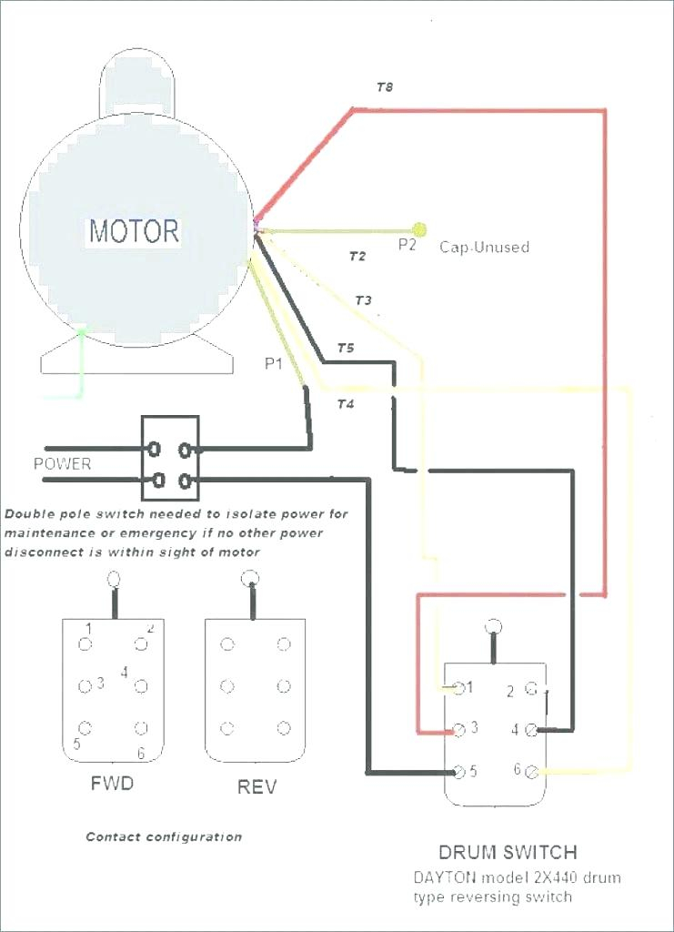
Leeson Single Phase Motor Wiring Diagram Esquilo Io

Wiring Diagram For Leeson Motor The wiring diagram of a leeson electric motor shows the various components of the motor, including the switches, wires, and other electrical components. it illustrates the relationship between these components and their function. the diagram also shows how the various parts are connected to each other. knowing this information is essential for. Leeson motor wire hook up. wire t3 wire t5 wire p2 (marked with yellow tape: do not modify) clear connector. x power. black wire white wire green wire wire nut. p1 t2 t4 ground screw p2. t3. wire nut.

Leeson Motor Wiring Schematic Dri vac corporation leeson brand motors single phase wiring diagrams 60hz low voltage leeson brand motors single phase wiring diagrams 50hz low voltage high voltage 3 high voltage o 04 o co ij2 5 o o ij3 ij2 rema dri vac corporation 45 ruby street • norwalk, ct 06850 p:203 847 2464 f:203 847 3609 info@remadrivac remadrivac . title. In a leeson 5 hp motor single phase wiring diagram, the switch is responsible for turning the motor on or off. it also controls the speed that the motor works at by allowing current to flow at certain speeds. when wiring up the switch, it should be located at the end of the line and be connected directly to the power source’s terminals. Referencing the leeson motor wiring diagram, connect the wires to the appropriate terminals on the motor. take note of the wire colors and make sure to match them correctly. use a screwdriver to securely tighten the terminal screws to ensure a solid electrical connection. 5. inspect and secure the connections. A single phase motor reversing contactor is an electrical device that is used to control the direction of rotation of a single phase motor. when a single phase motor is started, it requires a start winding to help it get up to speed. once the motor reaches its operating speed, the start winding is disconnected through a centrifugal switch.
Leeson Single Phase Motor Wiring Diagram Drivenheisenberg Referencing the leeson motor wiring diagram, connect the wires to the appropriate terminals on the motor. take note of the wire colors and make sure to match them correctly. use a screwdriver to securely tighten the terminal screws to ensure a solid electrical connection. 5. inspect and secure the connections. A single phase motor reversing contactor is an electrical device that is used to control the direction of rotation of a single phase motor. when a single phase motor is started, it requires a start winding to help it get up to speed. once the motor reaches its operating speed, the start winding is disconnected through a centrifugal switch. The leeson® brand spans more than 6,000 stock ac and dc motors, gearmotors and variable speed control solutions. all are built for rugged commercial and industrial applications. whether you need thousands of motors for oem applications or a single replacement motor, count on our twenty three. Routine and preventative maintenanceleeson motor electrical connectionsthe leeson 1.5 hp, 3450 rpm, 50 60 hz, single phase, fla 16.4, 115 230 volt motor is a compatible replacement motor for the ads standard line dishmachines. 15v), which includes af 3ds, et af, 5ags, l90 3dws, aws model families. it can also be used as the power scrapper.

Comments are closed.