Lucas Universal Alternator Wiring Diagram

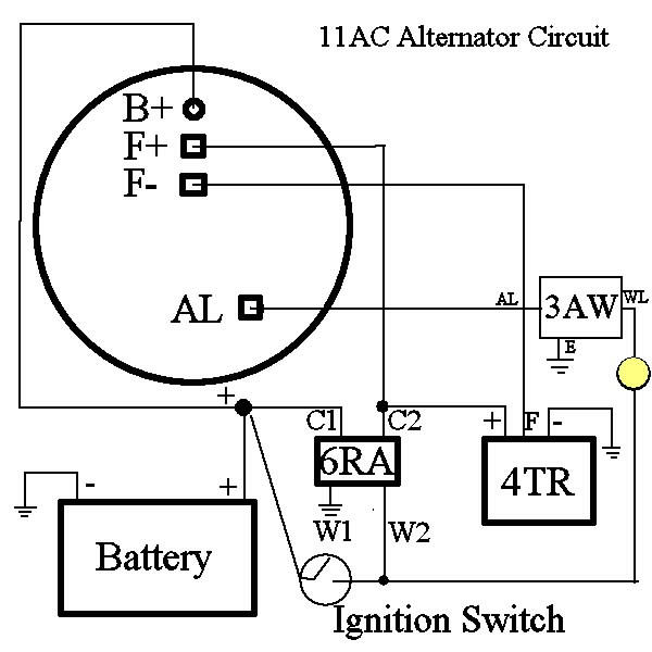
Lucas Universal Alternator Wiring Diagram Unhook all connections at the regulators. check the red wire: disconnect the red wire from alternator. turn the ignition switch to aux ("ignition") position. connect the end of the red wire to good ground, the warning light should glow. connect the end of the red wire to battery ( ), the warning light should go out. This video will take you through the basics of the a127 alternator.where the wiring goes and how to calculate your pulley ratio.
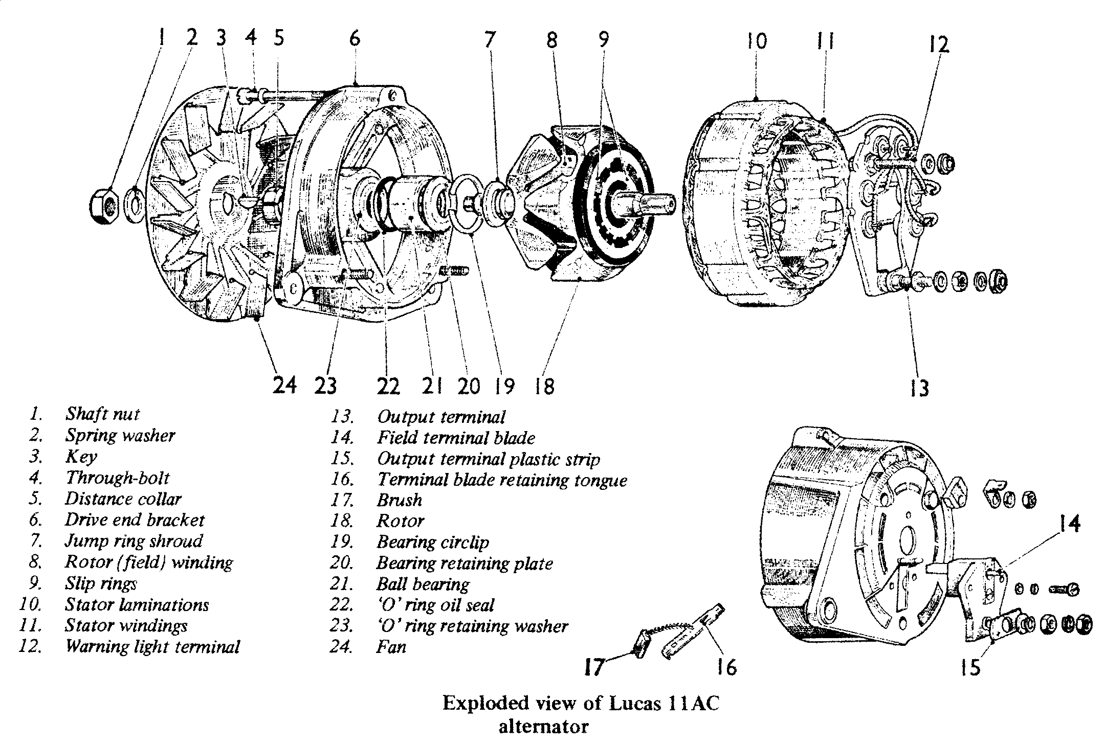
Lucas Universal Alternator Wiring Diagram Wiring Diagram And Schematics A lucas alternator wiring diagram will provide a step by step guide to ensure everything is wired up properly. it will also provide helpful tips and tricks on how to troubleshoot any issues that may arise. best of all, these diagrams are easy to read and understand, making them ideal for both beginners and experienced mechanics alike. A lucas alternator wiring diagram is a visual representation of the electrical connections between the alternator and the rest of the vehicle's electrical system. it is used by mechanics to troubleshoot and repair alternator problems. the alternator is a device that converts mechanical energy from the engine into electrical energy to power the. The lucas alternator wiring diagram is made up of various components that connect together to provide the necessary power to the alternator. at the center of the diagram is the alternator itself, which is connected to the engine via a drive belt. this is the main source of power for the alternator, and it’s essential that it’s properly. The lucas alternator wiring diagram provides a visual representation of the electrical connections and components of the alternator. it shows how the various wires and terminals are connected to the voltage regulator, ignition switch, battery, and other parts of the electrical system.

Lucas Universal The lucas alternator wiring diagram is made up of various components that connect together to provide the necessary power to the alternator. at the center of the diagram is the alternator itself, which is connected to the engine via a drive belt. this is the main source of power for the alternator, and it’s essential that it’s properly. The lucas alternator wiring diagram provides a visual representation of the electrical connections and components of the alternator. it shows how the various wires and terminals are connected to the voltage regulator, ignition switch, battery, and other parts of the electrical system. Open your car's hood and prop it up. disconnect both battery cables from the battery with a wrench and tuck them away from the battery terminals before proceeding. 2. locate your lucas alternator. locate your lucas alternator, which is made of aluminum and has vented sides through which you can view coils of brass wire. The lucas 3 wire alternator wiring diagram will usually include a legend that shows the symbols for each of the components. this makes it easier to determine which components are connected to which. additionally, the diagram will usually indicate the different colors of wires used in the installation. this helps you identify the correct wire.

Lucas Universal Alternator Wiring Diagram Open your car's hood and prop it up. disconnect both battery cables from the battery with a wrench and tuck them away from the battery terminals before proceeding. 2. locate your lucas alternator. locate your lucas alternator, which is made of aluminum and has vented sides through which you can view coils of brass wire. The lucas 3 wire alternator wiring diagram will usually include a legend that shows the symbols for each of the components. this makes it easier to determine which components are connected to which. additionally, the diagram will usually indicate the different colors of wires used in the installation. this helps you identify the correct wire.

Comments are closed.