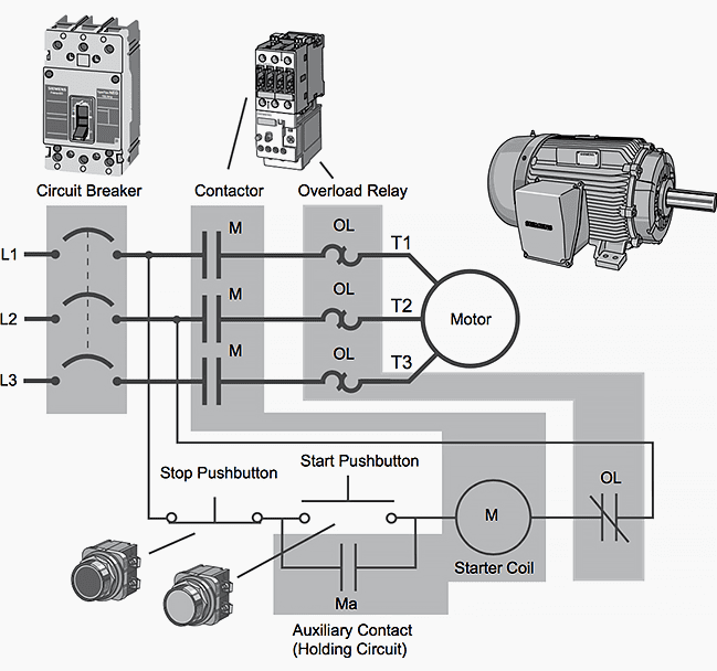
Magnetic Motor Starter Diagram

Electrical Wiring Diagrams Motor Starters 14. magnetic motor starters. for the control of three phase motors, magnetic contactors are used to open and close the power contacts in line with the motor. this allows for separation of the control circuit from the power circuit, providing greater safety for the operator and ease and convenience of wiring for the installer. Tion” diagrams, show the actual connection points for the wires to the components and terminals of the controller. they show the relative location of the components. they can be used as a guide when wiring the controller. figure 1 is a typical wiring diagram for a three phase mag netic starter. figure 1. typical wiring diagram.

Pin On Starter Wiring The magnetic motor starter is an electromagnetically operated set of contacts that starts and stops the connected motor load. a control circuit with momentary contact devices connected to the coil of the magnetic motor starter performs this start and stop function. a 3 pole full voltage magnetic motor starter is made up of the following. A typical magnetic starter wiring diagram will show the power supply connections, motor connections, and control circuit connections. it will also include information about the voltage and current ratings of the components, as well as any interlocks or safety devices that may be present. A single phase magnetic motor starter is used to control and protect an electric motor. the wiring diagram shows how the incoming power supply, motor, and control circuitry are connected together. the incoming power supply is connected to the l1 and l2 terminals, while the motor is connected to the t1 and t2 terminals. Required when a two wire control device is used. the bulletin 595 auxiliary contacts are designed as “a” and “b” on the wiring diagram. these contacts are easily. added to any allen bradley bulletin 500 starter sizes 0 through 4. when this system is used, the phase connections on all of the starters must be the same.

Wiring Diagram For Starter Motor A single phase magnetic motor starter is used to control and protect an electric motor. the wiring diagram shows how the incoming power supply, motor, and control circuitry are connected together. the incoming power supply is connected to the l1 and l2 terminals, while the motor is connected to the t1 and t2 terminals. Required when a two wire control device is used. the bulletin 595 auxiliary contacts are designed as “a” and “b” on the wiring diagram. these contacts are easily. added to any allen bradley bulletin 500 starter sizes 0 through 4. when this system is used, the phase connections on all of the starters must be the same. Step 1: gather the necessary tools and equipment, including the magnetic starter switch, wires, wire connectors, and a screwdriver. step 2: ensure the power source is turned off before starting the wiring process to avoid any potential hazards. step 3: identify the terminals on the magnetic starter switch. they are typically labeled as l1, l2. Magnetic starter motor connect power to the magnetic starter through the knock out plug in the top of the starter the magnetic starter is a large relay that switches high current from the main power line in response to a sig nal from the pressure switch. the national electric code and local codes. the compressor and starter must be.

Comments are closed.