Mobile Phone Jammer Schematic Iot Wiring Diagram

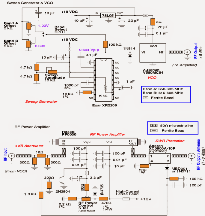
Gsm Signal Repeater Circuit Diagram Increase the frequency of tuned circuit by using this formula f= 1 (2*pi*sqrt (l*c)). increase the inductor capacitor circuit components value for increasing the frequency. get guide on mobile phone jammer circuit and its working. this circuit works in the range of 100m. and blocks the signals of cell phones. A cell phone jammer is a small equipment that is capable of blocking the transmission of signals between cell phones and base stations. this is mostly done by creating interference at the operating frequency ranges of cell phones, which results in no signal or significant loss of signal quality. although cell phone jammers could be used.

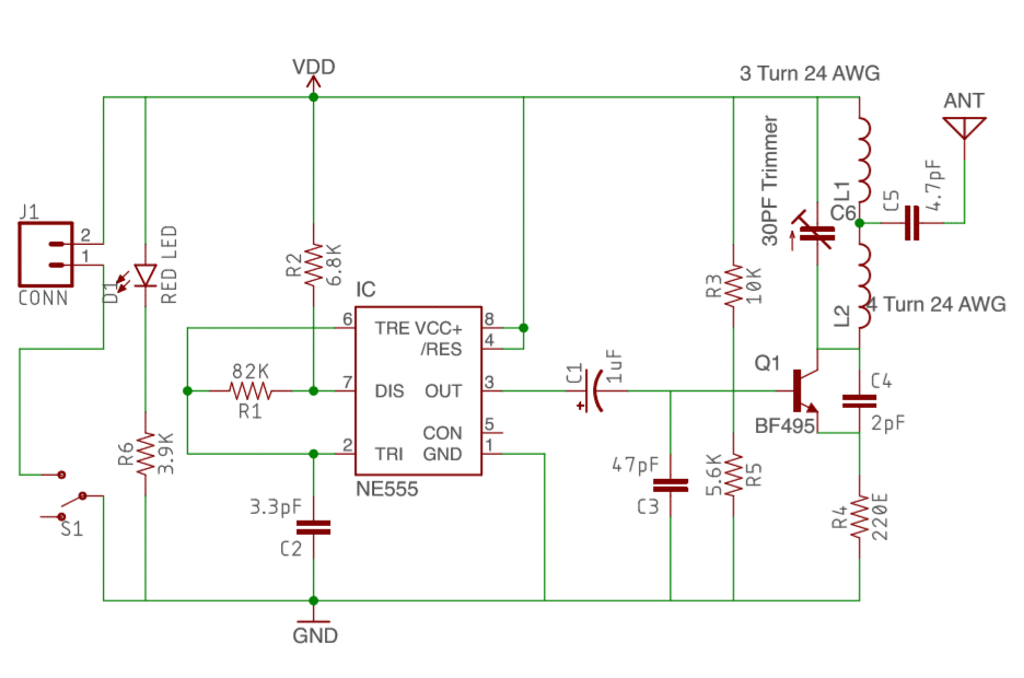
Mobile Phone Jammer Schematic Iot Wiring Diagram The use of different frequencies makes it difficult to have a jammer for all frequencies. however, the below mentioned formula can be used to calculate the required values. f = 1 (2*pi*sqrt(l1*c1)) depending on the frequencies you need to block, the values of the inductor (l1) and capacitor (c1) can be altered. In this project, i am going to make a cell phone signal jammer pcb (printed circuit board) using autodesk eagle which is used worldwide to design pcbs. in this project first, we will make the schematic and then we move to the board layout and complete our design. in this project we are going to use ne555 timer ic, resistors, capacitors both. A 4g mobile signal jammer circuit is an essential component of any security system, as it allows users to block out incoming transmissions from cell phones while still allowing them to send out their own. the 4g mobile signal jammer circuit, also known as a frequency jammer, works by emitting a signal that interferes with the signal of incoming. The switch s1 is used to turn on and turn off the cell phone jammer. in the above circuit the 555 timer is used as the frequency generator. the output of the 555 timer is fed to the amplifier circuit through a 1uf electrolytic capacitor. this capacitor blocks the dc and allow the ac signal to pass which is amplified by the transistor q1.

Comments are closed.