Mod 12 Hour Clock Using 4026 Ic Simulation Circuit By Inventive

Mod 12 Hour Clock Using 4026 Ic Simulation Circuit By Inventive I have made a project which is mod 12 hour clock using six 4026 ic , 555 timer ic and six 7 segment display (common cathod).this circuit works as 12 hour clo. In this video, i have made mod 12 counter ( 00 11 ) using 4026 ic and seven segment display.this circuit can be used for the hour part of a digital clock.i.

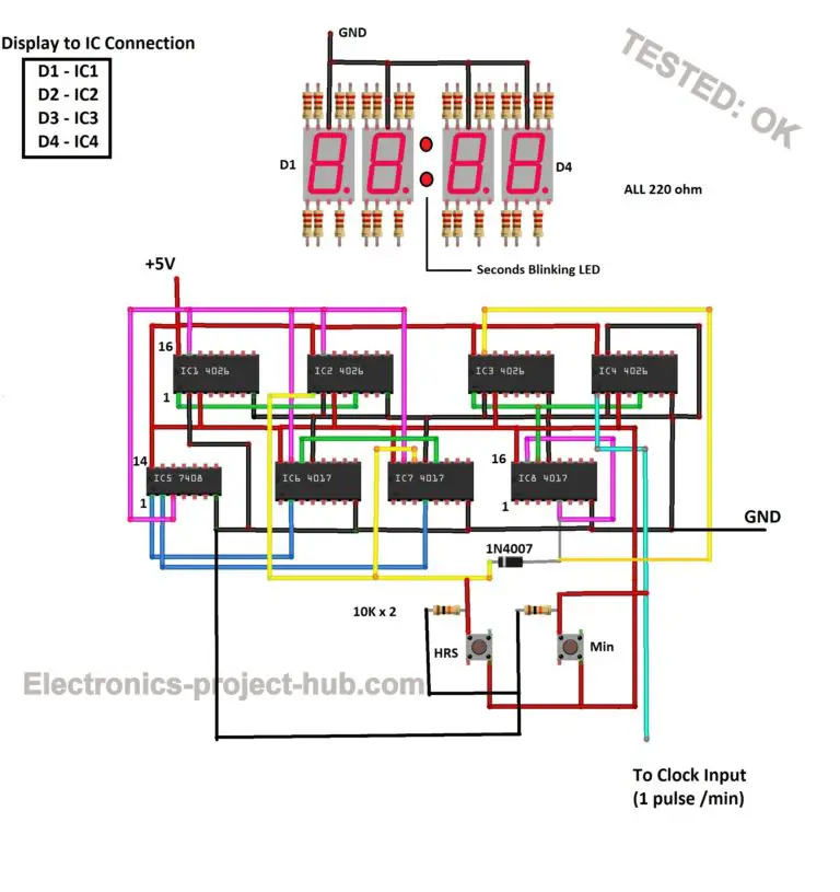
Analysis Of Counter Circuits All the circuit is power at 5v. note: the accuracy of this digital clock depends on how accurate you bring the ic 555 pulse to 1 hz. ic 4026 to 7 segment display connection: ic 4026 to 7 segment display connection. you need to connect the 220 ohm resistor to each segment as shown above. The two switch are used to set the time and is achieved using 4060 pin by increasing the frequency that is being fed to 4026 ic. the first switch which has lower frequency of the two is used to set the minutes in the clock. the second switch which has higher frequency is used to set the hours in the clock. 2. Date: march 1, 2021main components:1. cd 4026be (6) the 4026 is a decade counter integrated circuit (ic) with decoded outputs for driving a common cathode s. This circuit diagram is for a seven segment display driven by a 4026 decade counter, which receives the clock signal from a 555 timer ic. if you made the previous circuit to this, which used a push to make (ptm) switch to generate a clock pulse, then this circuit is a step forward and uses a 555 ic in astable mode to generate a slow clock pulse.

Digital Clock Circuit Diagram Using 7 Segment Display Date: march 1, 2021main components:1. cd 4026be (6) the 4026 is a decade counter integrated circuit (ic) with decoded outputs for driving a common cathode s. This circuit diagram is for a seven segment display driven by a 4026 decade counter, which receives the clock signal from a 555 timer ic. if you made the previous circuit to this, which used a push to make (ptm) switch to generate a clock pulse, then this circuit is a step forward and uses a 555 ic in astable mode to generate a slow clock pulse. Cd4026 is a 5 stage johnson decade counter belonging to a cd4000 series. it has many distintive features than other decade counters. firstly, it is ideal for applications having low power consumption requirement. secondly, cd4026 counts from 0 to 9 and then resets to 0. additionally, the advantage of using this ic is that it has a built in. Ic cd4026. 4026 ic is a 4000 series ic. it is a cmos seven segment counter ic and can be operated at very low power. it is a decade counter, counts in decimal digits (0 9). it is used to display numbers on seven segment displays and it increment the number by one, when a clock pulse is applied to its pin 1.

Interfacing 4026 With 7 Segment Display Engineersgara Vrogue Co Cd4026 is a 5 stage johnson decade counter belonging to a cd4000 series. it has many distintive features than other decade counters. firstly, it is ideal for applications having low power consumption requirement. secondly, cd4026 counts from 0 to 9 and then resets to 0. additionally, the advantage of using this ic is that it has a built in. Ic cd4026. 4026 ic is a 4000 series ic. it is a cmos seven segment counter ic and can be operated at very low power. it is a decade counter, counts in decimal digits (0 9). it is used to display numbers on seven segment displays and it increment the number by one, when a clock pulse is applied to its pin 1.

Comments are closed.