Non Inverting Integrator Electronics Tutorial

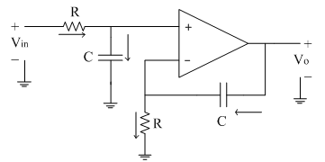
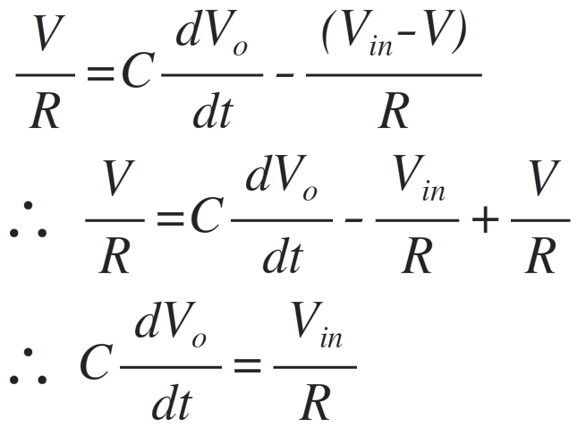
Non Inverting Integrator Electronics Tutorial The following circuit diagram shows the non inverting integrator. let the inverting terminal of op amp is at potential 'v' and hence non inverting terminal is also appears to be at the same potential 'v' due to virtual ground concept. input current to op amp is zero. hence at non inverting terminal node we have. Op amp integrator amplifier circuit.

Non Inverting Integrator Electronics Tutorial Figure 1: the basic inverting analog integrator consists of an op amp with a capacitor in its feedback path. (image source: digikey) the output voltage, v out, of the integrator as a function of the input voltage, v in, can be calculated using equation 1. equation 1. the gain factor of the basic inverting integrator is 1 rc applied to the. Non inverting operational amplifier configuration. Operational amplifier basics op amp tutorial. The integrator circuit outputs the integral of the input signal over a frequency range based on the circuit time constant and the bandwidth of the amplifier. the input signal is applied to the inverting input so the output is inverted relative to the polarity of the input signal. the ideal integrator circuit will saturate to the supply rails.

Comments are closed.