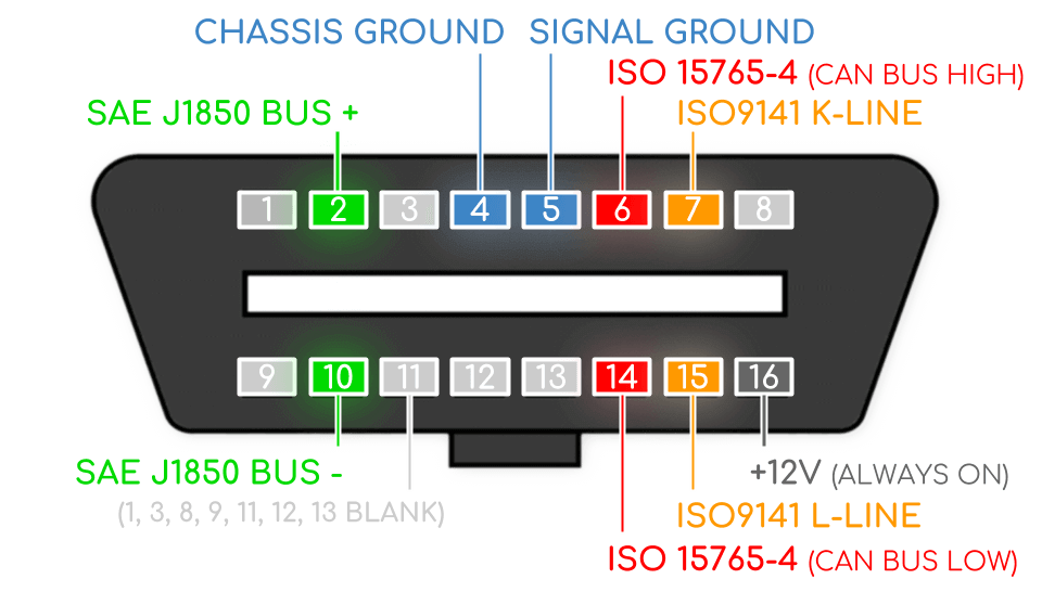
Obd2 Port Wiring Diagram Artus

Obd2 Diagnostic Port Wiring Diagram Understanding the basics of the obd2 port wiring diagram is crucial for diagnosing and troubleshooting any potential issues with your vehicle. the obd2 port wiring diagram typically consists of 16 pins, each serving a specific purpose. these pins are arranged in a specific pattern and have different functions, such as providing power, ground. Determine which ecm protocol your car has with these obd ii connector pinout diagrams obdii compliant vehicles can use up to five different protocols and multiple obdii connector pinout variations. • sae j1850 pwm • sae j1850 vpw • iso9141 2, • iso14230 4 (kwp2000), and • iso 15765 4 sae j2480.

Obd2 Port Wiring What Protocol Does Your Car Use вђ Obd2 Australia Obd ii diagnostic interface pinout. General motors (gm) obd ii diagnostic interface pinout. Obd2 pinout explained. major car brands pinouts. Obd2 pinout refers to the specific arrangement and configuration of pins within the standardized obd2 connector. the pinout determines the communication and electrical connections between a vehicle’s onboard computer system and an external diagnostic tool. understanding the obd2 pinout is crucial for effective diagnostics and troubleshooting.

Understanding The Obd2 Port Wiring Diagram A Comprehensive Guide Obd2 pinout explained. major car brands pinouts. Obd2 pinout refers to the specific arrangement and configuration of pins within the standardized obd2 connector. the pinout determines the communication and electrical connections between a vehicle’s onboard computer system and an external diagnostic tool. understanding the obd2 pinout is crucial for effective diagnostics and troubleshooting. 2010 l99 ls3 camaro ecm pinouts x1 x2. read the pinout x1 pin 27 28. do you know the pin location for odb ii plug? obd ii pins used. pins 1,2,&3: not used. pin 4: (black) ground, circuit 1050. pin 5: (black white) ground, circuit 1851. pin 6: (tan black) gm high speed lan serial data bus , circuit 2500, ecm x1 pin 28. pins 7 thru 13: not used. Type a is commonly found in cards, while type b is common in heavy & medium vehicles. both a & b types have similar obd2 pinouts, but the output power supply is different: 12v for type a and 24v for type b. there is a difference in the baud rate. the cars use approximately 500k, while most heavy duty vehicles use 250k. types of obd2 connector.

Comments are closed.