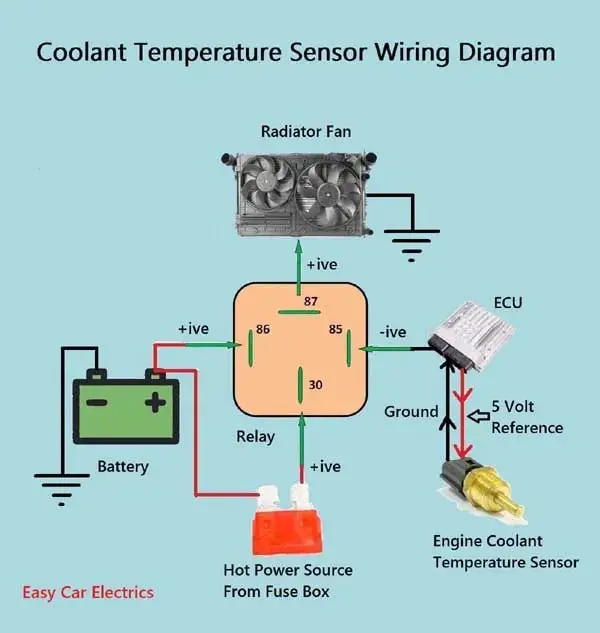
On Video Water Temperature Sensor Wiring Diagram Electrical And

On Video Water Temperature Sensor Wiring Diagram Electrical And The easy connection of water temperature sensor, ecu, water temperature guage , warning light, and check engine warning light. The wiring diagram of a water temperature sensor usually includes various components such as power supply connections, ground connections, and signal connections. the power supply connections provide the necessary electrical power to the sensor. the ground connections ensure proper grounding of the sensor for accurate temperature measurements.

The Wiring Diagram For The Temperature Sensor And Heater Driver With Verify the wiring: once you have created the connection diagram, double check the wiring connections to ensure accuracy. make sure the wires are securely connected to the appropriate terminals and there are no loose connections or short circuits. verify that the pt100 sensor is properly grounded and shielded. 3 wire coolant temperature sensor wiring diagram. the two wires, a “5 volt reference”, and a “ground wire” go to the ecu, and the third wire “earth 1 wire for temp gauge” goes to the cluster mounted temperature gauge by providing an earth link to the temperature gauge. in three wire coolant temp sensors, the ecu does not control the. This fan wiring diagram includes a fan relay, a temperature switch, and a this video shows how to easily wire an electric radiator fan circuit into any car. this fan wiring diagram includes a. Use a volt meter to ensure that there is power when the ignition is turned on. step 4: ground the gauge. connect the ground wire from the gauge to a clean, bare metal surface on the vehicle’s chassis. this ensures a solid ground connection and prevents any electrical interference. step 5: connect the sender wire.

Sensor De Temperatura Prova D гўgua Arduino Ntc 10kв 1 R 18 00 Em This fan wiring diagram includes a fan relay, a temperature switch, and a this video shows how to easily wire an electric radiator fan circuit into any car. this fan wiring diagram includes a. Use a volt meter to ensure that there is power when the ignition is turned on. step 4: ground the gauge. connect the ground wire from the gauge to a clean, bare metal surface on the vehicle’s chassis. this ensures a solid ground connection and prevents any electrical interference. step 5: connect the sender wire. A 3 wire pt100 wiring diagram is a diagram that illustrates how to properly connect a pt100 temperature sensor with three wires. pt100 is a type of resistance temperature detector (rtd) that is widely used in industrial applications to measure temperature accurately. it is designed to have a resistance of 100 ohms at 0 degrees celsius. Step 4: connect the wires. at this point, you will need to connect the wires from the pt100 sensor to the appropriate terminals on your measurement instrument or connector. refer to the wiring diagram or instruction manual for the specific wiring configuration, as it can vary depending on the instrument or application.

Cara Nak Buat Kipas Radiator Direct Kelisa Diagram A 3 wire pt100 wiring diagram is a diagram that illustrates how to properly connect a pt100 temperature sensor with three wires. pt100 is a type of resistance temperature detector (rtd) that is widely used in industrial applications to measure temperature accurately. it is designed to have a resistance of 100 ohms at 0 degrees celsius. Step 4: connect the wires. at this point, you will need to connect the wires from the pt100 sensor to the appropriate terminals on your measurement instrument or connector. refer to the wiring diagram or instruction manual for the specific wiring configuration, as it can vary depending on the instrument or application.
.jpg)
Coolant Temperature Sensor Wiring Diagram

Comments are closed.