Output Voltage Of The Blink Cycle Download Scientific Diagram

Output Voltage Of The Blink Cycle Download Scientific Diagram Download scientific diagram | output voltage of the blink cycle. from publication: the fusion of eye movement and piezoelectric sensing technology assists ceramic art process optimization and. Download scientific diagram | output voltage waveform of buck converter at 20% duty cycle. from publication: fourier series models of dc dc converters | the paper presents new models of dc dc.

Output Voltage 1 Phase Current 2 And Output Voltage Harmonics Similarly, for a slight increase in the duty cycle value from 0.5 to 0.75, the output voltage increases geometrically in magnitude to a peak value of vo = as shown in figure 9. this operation at d. Wabco abs is an electronic system that monitors and controls wheel speed during braking. the system works with standard air brake systems. abs monitors wheel speeds at all times and controls braking during wheel lock situations. the system improves vehicle stability and control by reducing wheel lock during braking. Download scientific diagram | buck regulator the average output voltage v=Øvs where Ø =duty cycle assuming a lossless current. the average current from publication: power factor corrected by. However in reality, during each half cycle the current flows through two diodes instead of just one so the amplitude of the output voltage is two voltage drops ( 2*0.7 = 1.4v ) less than the input v max amplitude. the ripple frequency is now twice the supply frequency (e.g. 100hz for a 50hz supply or 120hz for a 60hz supply.).

Output Voltage Current And Circulating Current Of Two Parallel Vsgs Download scientific diagram | buck regulator the average output voltage v=Øvs where Ø =duty cycle assuming a lossless current. the average current from publication: power factor corrected by. However in reality, during each half cycle the current flows through two diodes instead of just one so the amplitude of the output voltage is two voltage drops ( 2*0.7 = 1.4v ) less than the input v max amplitude. the ripple frequency is now twice the supply frequency (e.g. 100hz for a 50hz supply or 120hz for a 60hz supply.). The duty cycle is more commonly used than the mark space ratio. the formula for the duty cycle is: $$\text{duty cycle} = \frac{t {1}}{t} \text{ x } 100$$ a 50% duty cycle means the high time is equal to the low time. if an led is placed at the output of this astable circuit, it will turn on at the same span of time as it is turned off. Label the source voltage of the arduino (typically 5v). draw wires. draw lines to represent the wires that connect the components. label the wires to indicate their purpose, such as “led to d13,” “resistor to gnd,” and so on. your wiring diagram should illustrate how all these components are connected in the circuit.

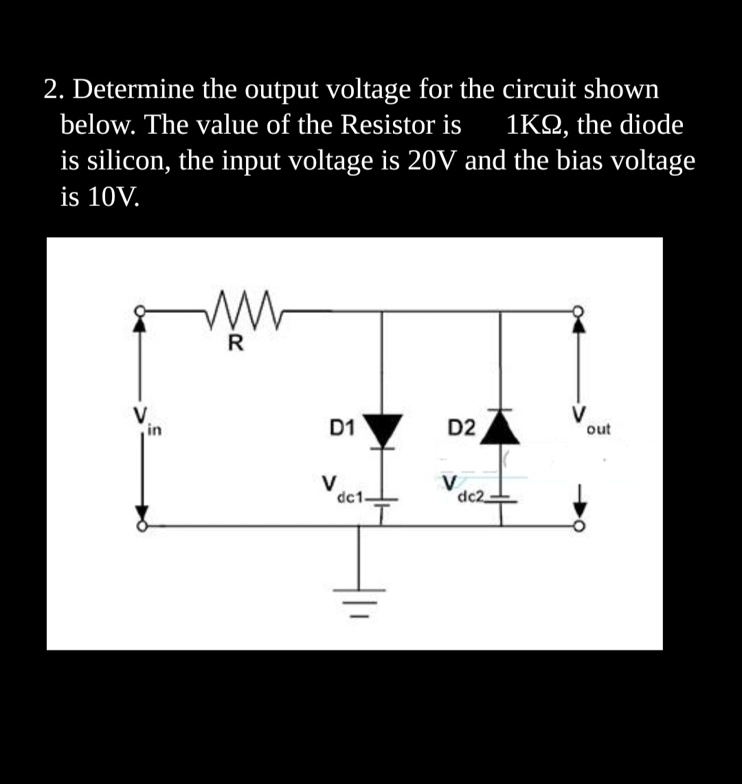
Answered 2 Determine The Output Voltage For Theвђ Bartleby The duty cycle is more commonly used than the mark space ratio. the formula for the duty cycle is: $$\text{duty cycle} = \frac{t {1}}{t} \text{ x } 100$$ a 50% duty cycle means the high time is equal to the low time. if an led is placed at the output of this astable circuit, it will turn on at the same span of time as it is turned off. Label the source voltage of the arduino (typically 5v). draw wires. draw lines to represent the wires that connect the components. label the wires to indicate their purpose, such as “led to d13,” “resistor to gnd,” and so on. your wiring diagram should illustrate how all these components are connected in the circuit.

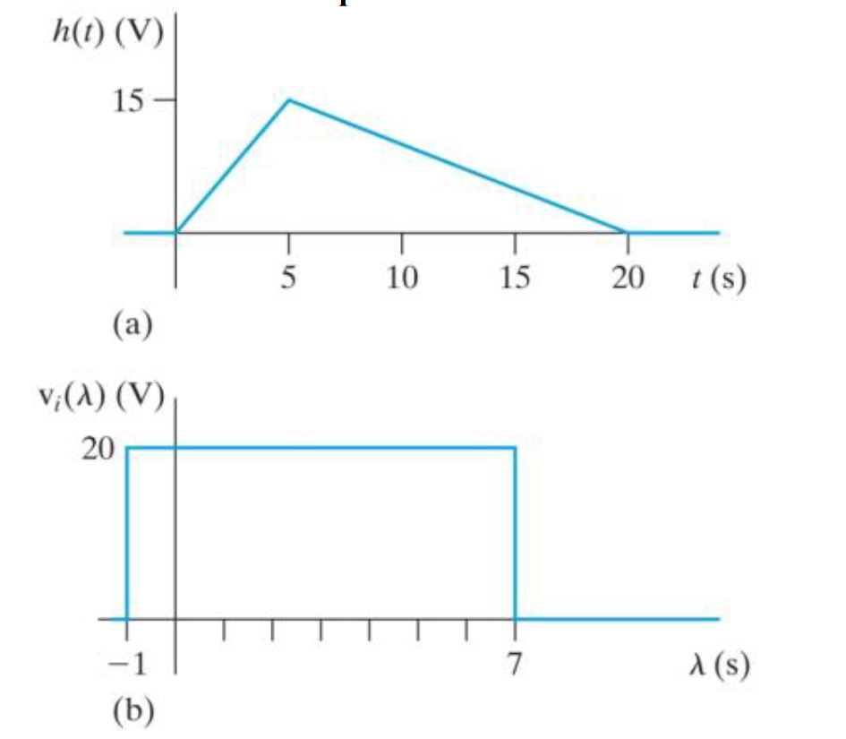
The Voltage Impulse Response Of A Circuit Is Shown Chegg

Comments are closed.