Peltier Cooler Schematic Diagram

Peltier Cooler Circuit Diagram This tec1 12706 module and the peltier effect makes the perfect diy cooler! this instructable is a step by step tutorial showing you how to make your homemade cooler. this diy fridge uses the peltier effect, which is the presence of heating or cooling at an electrified junction of two different conductors. The simple construction of a simple peltier refrigerator circuit shown in the figure demonstrates the above discussed set up where two such devices are appropriately fixed with aluminum plates for radiating different degrees of temperatures from their relevant sides. the plates responsible for generating the cooling effects must be trapped.

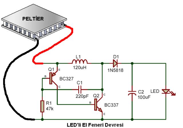
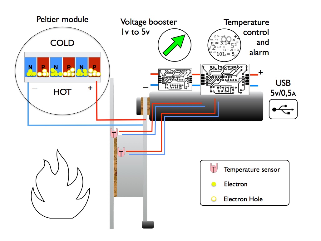
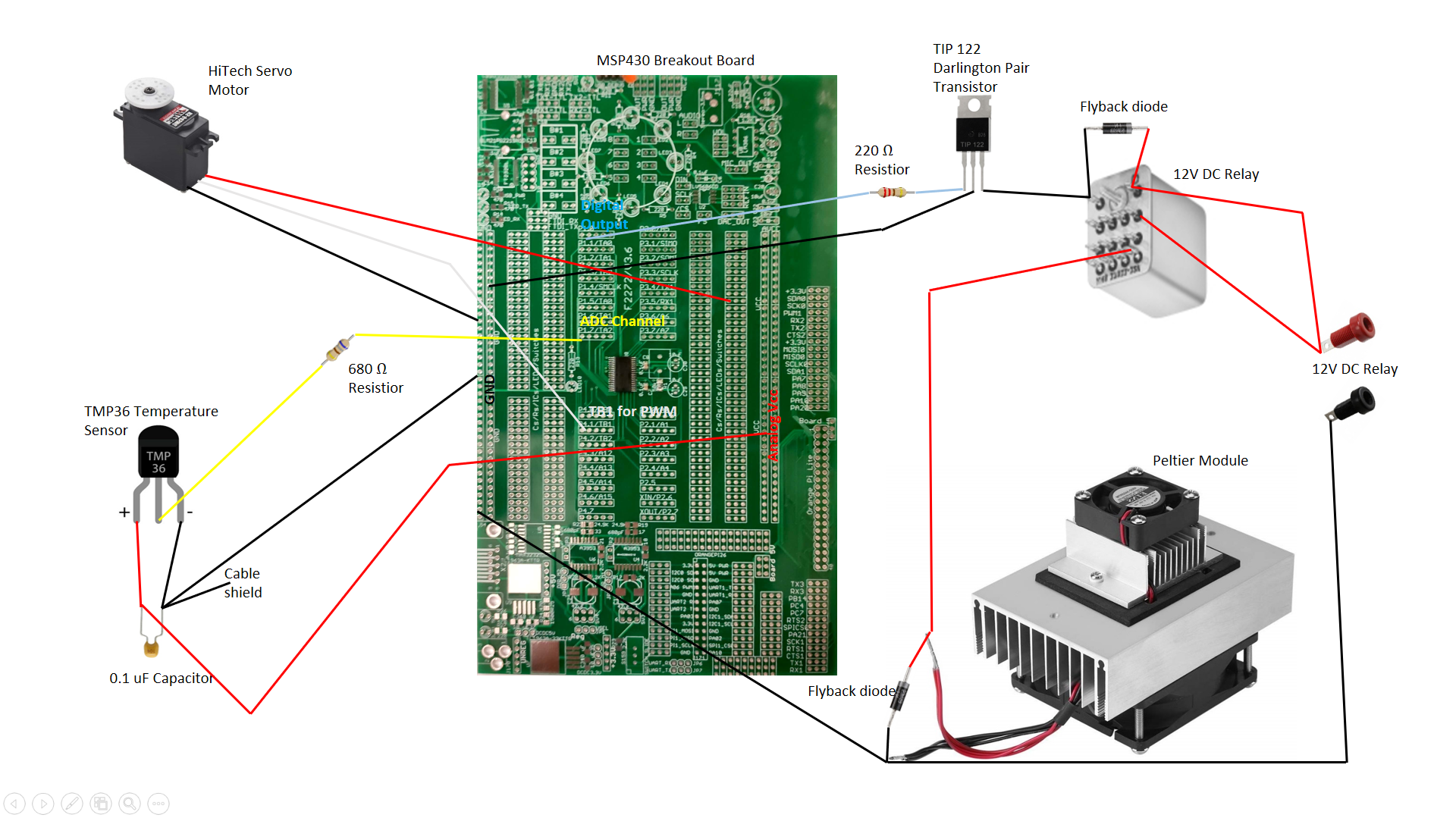
Peltier Cooler Circuit Diagram In a nutshell, a peltier module circuit diagram is a visual guide showing how electrical current flows into and out of the peltier module. it provides an easy to follow reference for installing and connecting the module, as well as the proper voltage and resistance settings. the diagram also allows users to see the relationship between the. The peltier module acts as a heat pump when an electric current is applied to the module. one side of the peltier is cooled while the other gets hot. there are two main types of modules taking advantage of the peltier effect; the thermoelectric cooler (tec) and the thermoelectric generator (teg). the teg can stand higher temperatures and tends. The circuit diagram is used to understand how the cooler works, and how to connect the device to other components in the system. it includes components such as the power source, the peltier cooler, a voltage regulator, as well as switches and sensors. understanding the circuit diagram is important, as it helps determine the correct current and. Figure 2: peltier module system design with constant voltage. however, in other applications, peltier modules are implemented to maintain an object at. controlled temperature. these designs utilize a thermal sensor, such as a thermocouple, solid state temperature sensor, or an infrared sensor to monitor the temperature of the object.

Peltier Cooler Hackster Io The circuit diagram is used to understand how the cooler works, and how to connect the device to other components in the system. it includes components such as the power source, the peltier cooler, a voltage regulator, as well as switches and sensors. understanding the circuit diagram is important, as it helps determine the correct current and. Figure 2: peltier module system design with constant voltage. however, in other applications, peltier modules are implemented to maintain an object at. controlled temperature. these designs utilize a thermal sensor, such as a thermocouple, solid state temperature sensor, or an infrared sensor to monitor the temperature of the object. 2 definition of peltier efficiency. this section gives an overview about the performance that can be reached using a reasonable amount of power. for this test, a 17.9 w, 3.9 a, 7.6 v, 30 mm x 15 mm et 063 10 13 peltier module is used. the performances can be defined by the difference of temperature between the ambient temperature and the cold. 1.1 a thermoelectric (te) cooler, sometimes called a thermoelectric module or peltier cooler, is a semiconductor based electronic component that functions as a small heat pump. by applying a low voltage dc power source to a te module, heat will be moved through the module from one side to the other. one module face, therefore, will be cooled.

Comments are closed.