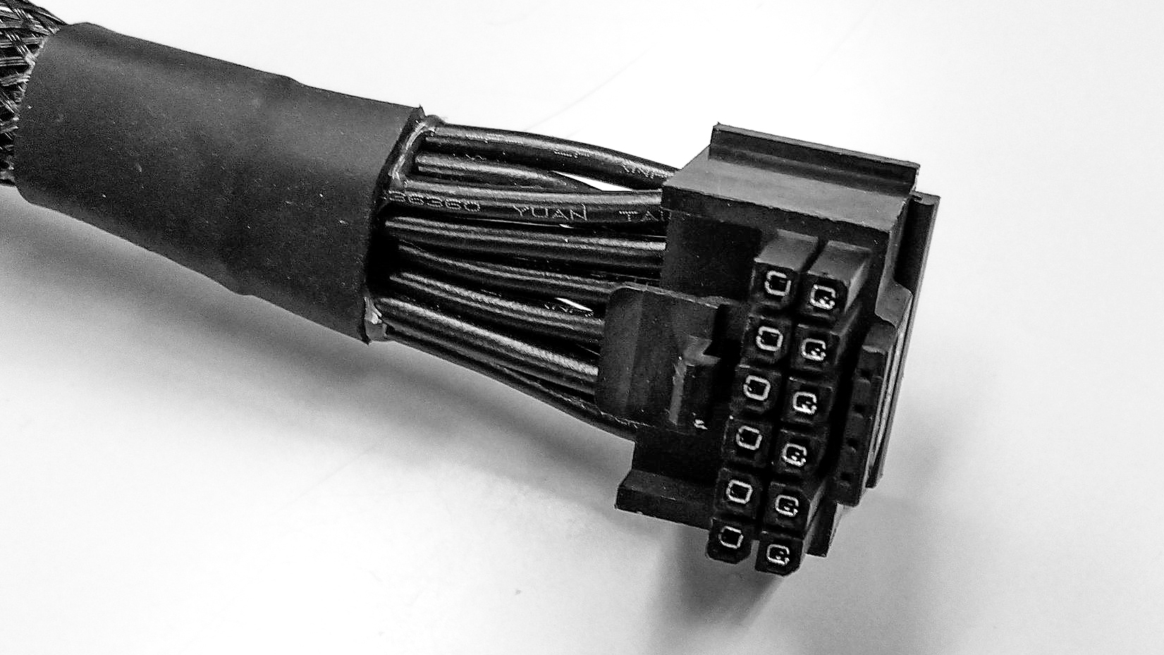
Pin En 16

Psl 16 Pin Connector 16 Pin With Interlock Straight At Reichelt The esp32 has two i2c channels and any pin can be set as sda or scl. when using the esp32 with the arduino ide, the default i2c pins are: gpio 21 (sda) gpio 22 (scl) if you want to use other pins when using the wire library, you just need to call: wire.begin(sda, scl);. Esp32 peripherals and i o. although the esp32 has 48 gpio pins in total, only 25 of them are broken out to the pin headers on both sides of the development board. these pins can be assigned a variety of peripheral duties, including: 15 adc channels. 15 channels of 12 bit sar adc with selectable ranges of 0 1v, 0 1.4v, 0 2v, or 0 4v. 2 uart.

Simplifying 16 Pin 12vhpwr Pcie5 Connector And Why You Need It Pc Esp32 pinout. the esp32 module comes in various variants, but we will focus on the commonly used esp wroom 32 module, which offers 38 gpio pins. below is the detailed description of the esp32. Esp32 is a dual core soc with two powerful xtensa lx6 cpus that run at up to 240 mhz. it comes with integrated wi fi and bluetooth connectivity, making it suitable for a wide range of iot applications that require wireless connectivity. esp32 is the successor of the popular esp8266 chip, and it offers a lot more capabilities and functionality. The enable pin is crucial for controlling the power supply to peripherals, allowing efficient power management. the enable pin is the one labeled en on the esp32 development board. an en button is also found near the microusb port. remember that when en is pulled low, the esp32 is disabled. when the en pin is high or left as is, the esp32 is. The en pin can activate or deactivate the esp32 via an external wire. it is connected to the board’s en button. when the esp32 is on, it is at 3.3v. if you put this pin to the ground, the esp32 is off. this can be used when the esp32 is in a box and you want to be able to turn it on off with a switch.

Right Angle 16 Pin Connector May Save A Lot Of Rtx 4090 Gpus Updated The enable pin is crucial for controlling the power supply to peripherals, allowing efficient power management. the enable pin is the one labeled en on the esp32 development board. an en button is also found near the microusb port. remember that when en is pulled low, the esp32 is disabled. when the en pin is high or left as is, the esp32 is. The en pin can activate or deactivate the esp32 via an external wire. it is connected to the board’s en button. when the esp32 is on, it is at 3.3v. if you put this pin to the ground, the esp32 is off. this can be used when the esp32 is in a box and you want to be able to turn it on off with a switch. When the en pin is pulled to gnd, it resets the esp32 boards. it’s the same thing as pressing the on board reset button. so, you can connect a pushbutton to the gpio labeled as en. you should wire the pushbutton so that when it is pressed, it connects to gnd. this way, when you press that button the esp32 will reset. i hope this helps. The esp32 includes 2 8 bit dac (digital to analog) pins. the 8 bit resolution means that these converters can produce a voltage between 0 and 3.3v with the accuracy of 3.3 256 volts. these 2 pins are as follows. dac1 (gpio 25) dac2 (gpio 26) it is illustrated in the following esp32 pinout image:.

Pcie Gen5 Graphics Cards Will Need 16 Pin Power Cable Or вђњ3г 8 Pin To 16 When the en pin is pulled to gnd, it resets the esp32 boards. it’s the same thing as pressing the on board reset button. so, you can connect a pushbutton to the gpio labeled as en. you should wire the pushbutton so that when it is pressed, it connects to gnd. this way, when you press that button the esp32 will reset. i hope this helps. The esp32 includes 2 8 bit dac (digital to analog) pins. the 8 bit resolution means that these converters can produce a voltage between 0 and 3.3v with the accuracy of 3.3 256 volts. these 2 pins are as follows. dac1 (gpio 25) dac2 (gpio 26) it is illustrated in the following esp32 pinout image:.

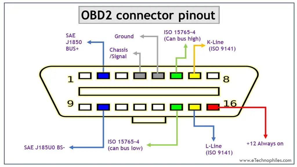
16 Pin Obd Connector Pinout

Comments are closed.