Pin On Layout

Pin Layout On Raspberry Pi Raspberry Valley The above example defines a default layout that has three pinned items: notepad, the calculator uwp app, and command prompt. adding pins to your layout. pin classic windows applications or universal windows apps to your taskbar by adding up to three elements under the <taskbar:taskbarpinlist> element:. Obd 2 pinout explained. on board diagnostics ii, or obd2, is a self diagnostic and reporting system in modern vehicles. it consists of an electronic control unit, several sensors, and indicator lights. the sensors inspect the various subsystems within the vehicle and report any faults and abnormalities to the ecu.

Pin Layout On Raspberry Pi Raspberry Valley The rj45 connector is a standardized solution for terminating network cables. it follows the tia eia 568 standard, which specifies the pinout and wiring scheme for ethernet cables. the rj45 connector has eight pins arranged in two rows of four. pins 1 and 2 are used for transmit data, pins 3 and 6 are used for receive data. The next pinout diagram below is the counterpart for the more detailed isometric and t 568 b rj 45 wiring above, showing rj45 pin numbers and color order for t 568 a. can you pick which pairs are swapped relative to the t 568b wiring diagram? t568a wiring diagram with rj45 pin numbers and wiring order:. Overall, wiring a 6 pin on off on rocker switch in an on off on configuration requires understanding the pin layout and making the appropriate connections. by following the wiring diagram and taking proper precautions, you can ensure that the switch functions as intended and provides control over multiple circuits or functions. A pinout is a diagram or listing of the electrical connections (pins) inside an electronic component or circuit board. there is often a standard pinout used for a given component or pcb. pinouts can be used to connect wires or to troubleshoot the operation of an electronic device. computer power pinout. for example, a common computer power.

The Definitive Arduino Uno Pinout Diagram Overall, wiring a 6 pin on off on rocker switch in an on off on configuration requires understanding the pin layout and making the appropriate connections. by following the wiring diagram and taking proper precautions, you can ensure that the switch functions as intended and provides control over multiple circuits or functions. A pinout is a diagram or listing of the electrical connections (pins) inside an electronic component or circuit board. there is often a standard pinout used for a given component or pcb. pinouts can be used to connect wires or to troubleshoot the operation of an electronic device. computer power pinout. for example, a common computer power. Pin 7: k line pin 15: l line (optional) physical layer identical to iso 9141 2 data rate 1.2 to 10.4 kbaud message may contain up to 255 bytes in the data field iso 15765 can (250kbit sec or 500kbit sec) pin 6: can high pin 14: can low used in most modern vehicles. note that pins 4 (battery ground) and 16 (battery positive) are present in all. The micro:bit has 25 external connections on the edge connector of the board, which are referred to as ‘pins’. the edge connector is the gold area on the right side of board as shown the figure below. there are 5 large pins that are also connected to holes in the board labelled: 0, 1, 2, 3v, and gnd. and along the same edge, there are 20.

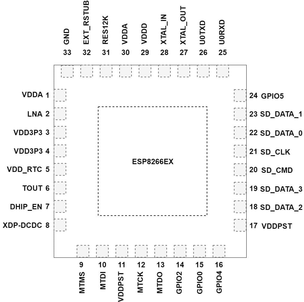
Esp8266 Pinout Reference And How To Use Gpio Pins Pin 7: k line pin 15: l line (optional) physical layer identical to iso 9141 2 data rate 1.2 to 10.4 kbaud message may contain up to 255 bytes in the data field iso 15765 can (250kbit sec or 500kbit sec) pin 6: can high pin 14: can low used in most modern vehicles. note that pins 4 (battery ground) and 16 (battery positive) are present in all. The micro:bit has 25 external connections on the edge connector of the board, which are referred to as ‘pins’. the edge connector is the gold area on the right side of board as shown the figure below. there are 5 large pins that are also connected to holes in the board labelled: 0, 1, 2, 3v, and gnd. and along the same edge, there are 20.

Raspberry Pi 4 Model B Pin Layout

Comments are closed.