Pin On Positive

Pin On Enamel Pins Apr 29, 2015 at 14:37. 1. the end that measures positive with your multimeter is positive, and the end that measures negative is negative (assuming you have one at an actual wallwart) – plasmahh. apr 29, 2015 at 14:38. 1. @rdrast: in my experience the sleeve is the negative more than about 80% of the time. this seems to be some kind of rule. Attach 1 lead to each wire. clip the small alligator clip on the red lead to the end of 1 wire and the clip on the black lead to the end of the other. look at the reading on the screen—you'll see a number and either a or – sign. [8] the number is the voltage reading. the indicates positive current.

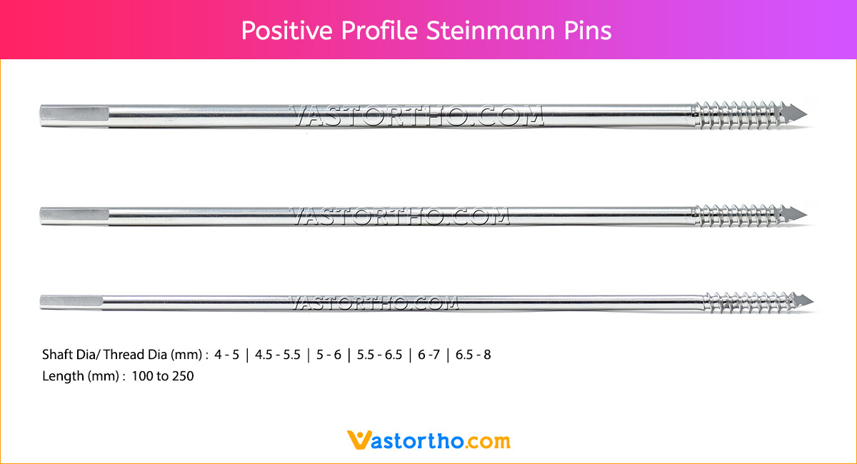
Positive Profile Steinmann Pin Uses Sizes Surgical вђў Vast Ortho There are two pin connectors for each, and some might display an arrow indicating the implied positive side, but it doesn't matter which way you connect a switch. Here pin 3 will got to the battery, pin 2 & 1 to the circuit. when you plug in the socket pin 1 & 2 would provide the power to the circuit and battery will be disconnected. when unplugged the battery would be connected back to the circuit. though there are other configuration also in which it can be used but this is a simple example which might. The third pin is usually found on li poly, or lithium polymer batteries and is required in order to charge the battery safely. because these batteries are usually multi cell, the third pin is used for balancing the charge between each of the cells. share. cite. answered feb 23, 2011 at 16:44. So i'm trying to understand the pin layout of an ethernet port, specifically for 8p8c which to my understanding is the most common. of the eight pins, only four are apparently used for communication, as depicted below where pin 1 and 2 are td and td , and pin 3 and 6 are rd and rd . (where td = transmit, rd = receive).

Positive Sign Enamel Pin Pin And Patches Enamel Pins Patches The third pin is usually found on li poly, or lithium polymer batteries and is required in order to charge the battery safely. because these batteries are usually multi cell, the third pin is used for balancing the charge between each of the cells. share. cite. answered feb 23, 2011 at 16:44. So i'm trying to understand the pin layout of an ethernet port, specifically for 8p8c which to my understanding is the most common. of the eight pins, only four are apparently used for communication, as depicted below where pin 1 and 2 are td and td , and pin 3 and 6 are rd and rd . (where td = transmit, rd = receive). Example 1. 4 pin (normally open) relay with the switch on the positive side of the control circuit. example 2. 4 pin (normally open) relay with the switch on the negative side of the control circuit. note: these circuits have been simplified to illustrate the function of a relay and therefore exclude fuse protection that would be required. This diagram shows the common xlr pinout for 5 pin xlr connectors. this connector is commonly used for lighting control via dmx, although i’ve also seen it used for some power supplies and party line comms systems. here is the dmx 5 pin xlr pin out: pin 1: shield (common) pin 2: dmx 1 negative. pin 3: dmx 1 positive. pin 4: dmx 2 negative.

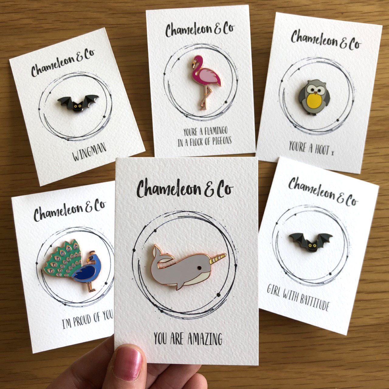
Positive Pin Button Badge Positive Quotes Pin Badge Metal Etsy Example 1. 4 pin (normally open) relay with the switch on the positive side of the control circuit. example 2. 4 pin (normally open) relay with the switch on the negative side of the control circuit. note: these circuits have been simplified to illustrate the function of a relay and therefore exclude fuse protection that would be required. This diagram shows the common xlr pinout for 5 pin xlr connectors. this connector is commonly used for lighting control via dmx, although i’ve also seen it used for some power supplies and party line comms systems. here is the dmx 5 pin xlr pin out: pin 1: shield (common) pin 2: dmx 1 negative. pin 3: dmx 1 positive. pin 4: dmx 2 negative.

Positive Pin Positive Affirmation Pin Badge Positive Message Etsy

Comments are closed.